This blog is a lab notebook for my work with the Reprap open source 3D printing undertaking.
Sunday, February 21, 2010
Stumbling across the biopolymer zein
It is hard to find time to hare after all of the potential research directions implicit in the Reprap undertaking. As a result of that, I've tried to concentrate on just a few areas dealing with the increase of the printed percentage of Reprap machines. Yesterday, however, I got off-track for a few hours.
For some reason I found myself looking for the Wikipedia entry for bioplastics and serendipitously keyed in biopolymers instead. There, I ran across a reference I hadn't seen before about a biopolymer called zein. The article referenced an incredibly detailed review of the material concentrating on its extraction written up a few years ago by John W Lawton at the USDA laboratory at Peoria in Illinois. Apparently, there is a large collection of zein related articles there which served as the basis of Lawton's extensive article. A few things about zein jumped out at me.
The biggest was that it was a protein, biopolymer which used corn gluten meal, a rather useless byproduct of the corn milling process. Corn gluten meal is a non-nutritive waste product that is typically used as a bulk agent for cattle fattening. It also has developed a small reputation as an "organic" herbicide for home gardens. This last is important because it means that 50 lb sacks of it can be had by ordinary people in one-off quantities at prices of under $1/lb. What that implies is that corn gluten meal is basically free and that what you are looking at is mostly the packaging, warehousing and transport cost when you purchase it.
The second was that reading over the Lawton article that the most successful extraction methods were achieved with kitchen chemicals {rubbing alcohol with a touch of lye} and chemistry. As well, zein has a long history of being used as a plastic, coating and, interestingly a fibre. This last I will talk about a bit later in this blogging.
Zein was used extensively before being displaced by petroleum-based substitutes during the 1950s and 1960s. Currently, ready-to-use zein is quite expensive {~$10-25/lb} not because of its intrinsic cost but rather because its very limited market, viz, food grade coatings for pills and food products commands such prices due to its highly regulated nature.
I vaguely remember from my childhood a wool substitute fiber called Vicara which emerged in the 1950s before being replaced by synthetic, petroleum-based fibers a decade or so later. What shool me about the Lawton article was that Vicara was made from zein. The rather high softening temperature of Vicara {~245 C}. If the melting temperature of zein is anywhere near this a whole range of products like coffee makers and the like become possible. Using PEEK instead of PTFE for thermal barriers in extruders, something that we are already beginning to do regularly, ought to let us get by with that.
Oddly, zein's glass transition temperature is very low {~40 C}. It may be that like PLA, zein has no real warping problem during printing compared to petroleum-based polymers.
Heretofore, our use of plastic filament as feedstock for printing has caused practical problems when mapped against our desire for a recycling scheme for plastic. With recycling we have to grind the waste plastic, a problem that appears to have been solved recently. Afterwards, we have to extrude the filament. The machinery for doing this extrusion is relatively complicated. Sadly, you can't just extrude filament. After it is extruded you have to quench, reheat and run it through a series of godet stations before you can spool it. This videoclip gives you a fair notion of the complexity and scale of the process. It seems to me that scaling down that sort of process is going to be an undertaking much more complicated than the Reprap printer
The notion that zein was made into fiber coupled with the application of electrospinning to zein fibres led me to quite a new idea. What would stop us from using spun fiber instead of monofilament in our extruders?
Electrospinning can be achieved with very simple apparatus such at this piece of lab equipment made in New Zealand.
Spinning the filament into thread of the proper diameter is an old, old technology easily scaled to our application. This Indian charkha shows how simple the technology can get.
Filament is useful in our extrusion technology because it is stiff enough to be forced into our extruder barrel under pressure. Obviously, fibre thread can't. Keeping in mind, however, that our thread is polymer, we should be able to draw it through a heated die to consolidate the fibres into a single polymer mass.
Thursday, February 18, 2010
End to end
I wrote a routine that serially checks paths and reverses them, if necessary, to minimize the travel distance between one path and the next. Basically, I look at the end points of each path, then print the first path and compare its trailing end with the end points of the next path. I then choose the nearest one. If it is the leading point then I print the path as is. If it is the trailing point, then I reverse the path and then print it.
As you might imagine, it greatly reduces the print time and makes for a much cleaner printed raft.
I now have all of the routines running more or less properly to print objects. That comes next.
Sunday, February 14, 2010
Got the perimeters going
I wanted to do a direct translation of my XML format to gcode instead of breaking it into perimeters and infill as I had it before. The way I did it previously worked fine as long as you only wanted the possibility for one kind of infill. I'd like to a little better than that this time.
I've got a bit more work to do getting the ends of the infill to match a little better with the perimeter, but for now it is working pretty well. The brown bits are fried ABS that fell off the extruder head. I should have cleacked to see that it was clean before starting the print.
You can see a little misalignment of the perimeter of the raft. It turned out that the grub screw on the stepper side of the y-axis had shaken loose. Fifteen minutes of fishing around in the pocket in the acrylic assembly that it had fallen into with a hemostat recovered it. Once reinstalled, the misalignment disappeared. :-)
Saturday, February 13, 2010
The raft {infill module} works
Luckily, I was able to isolate the alignment problem to a loose y-axis belt pulley.
You can see that the alignment is perfect this time. The missing bit of print path happened because that path was the first one printed and the printed filament broke loose for about a centimeter from the point of first contact.
Now, on to checking out the module that does the perimeter.
It's rude, it's crude ...
... it's socially unacceptable. Slice and Dice is my code, however, and when I want to try something new I can just dive into the code without having to ask anybody anything.
Right now, I'm doing test prints for a fitted raft for a small, rectangular block. As you can see, I have a problem with the alignment between the two layers of the raft. The roughness of the second layer is happening because I haven't got around to arranging the print roads end-to-end yet. Sorting out the alignment comes first.
I've also tried printing out a few layers of the block itself. I've got a bit of trouble with the perimeter which I hope to get sorted out later today.
Having a printer sitting next to the PC I'm developing the Slice and Dice code on that can test code changes in a matter of a few minutes is a real blessing.
Monday, February 08, 2010
The latest and greatest from Skeinforge
Skeinforge continues to exhibit bizarre behaviour when you use the multiply feature.
All that was changed between these two runs was the number of the same item being printed. The one on the left printed 2 beam segments while the one on the right printed four.
Saturday, February 06, 2010
Testing the envelope
This has been a pretty frustrating week. Last week I got a long way towards evolving a thin-walled approach to making post-tensioned, composite structures which could support herringbone rack and pinion systems. This week I wanted to push the post-tensioned theme a bit further and decided to see what issues were involved in printing an open structure beam/column system.
For a first pass, I developed this stackable, interlocking beam module.
It was a bear to create with Art of Illusion, but with Netfabb to clean up AoI's nasty STL files I managed, finally, to make it happen.
I did some preliminary partial prints to see what the issues were and discovered that I could either print one segment using the Sleinforge cooling option and wind up many hours later with a column segment that was festooned with strings of ABS ooze OR I could print several in the same time which required much less after-the-print cleanup.
That is when the trouble started. In the several days prior to this exercise I'd discovered that I could print the column section for the herringbone rack at 32 mm/sec without a serious degradation in print quality. This made printing these beam segments much less daunting a task. When I began, however, I ran into a nasty concatenation of disasters that pretty much ruined my printing week. The first one occurred when I started a print and shortly after was called away for about 45 minutes to help my sister install a new wireless printer she'd bought.
When I returned to the lab I discovered that my Rapman 3 had partially reset whilst printing the raft for the segment leaving the extruder running. This unfortunate situation burned a small pit in my print table and buried my Kapton tape extruder head in a big blob of molten ABS. The Kapton tape extruder head had been happily running since October, I believe, without complaint. Being buried in ABS, however, pretty much put an end to it.
Fortunately, I'd bought several of BitsFromBytes new pre-made, silicone covered extruder heads. After about an hour swapping out the old, ruined head for the new one I was printing again ... almost. There was, of course, the usual running in of a new part. The new head was about 3 mm shorter than the old one, so I had to go through the whole adjusting for the new print height thingy, complete with printing new trial rafts and the like.
That done, I went back to trying to generate a set of four of the beam segments with Skeinforge. Months ago, I'd downloaded the latest release, August's. Skeinforge these days is a busy, overcomplicated piece of software which has far too many bells and whistles hung off of it. In concept and execution, however, it is a brilliant piece of work.
That said, my column segment exercise pushed right though Skeinforge's performance envelope. It appears that when you create a BFB file with more than a million lines of gcode in it, that the August version of Skeinforge simply runs out of memory and blows up in the Export routine. After several false starts I finally got the most recent release of Skeinforge down and sort of working. The memory problem was gone, but in its place was a total buffet of new bugs relating to both the Multiply option and the Speed option. The two options appear to interact to produce some really bizarre gcode.
I'd hoped by now to have the new Netfabb gcode generator. Sadly, the Netfabb people have discovered that the developing of that app was a bit bigger task than they'd originally thought, so the release date got pushed back from 1 February to 1 March. That left me with either going back to my old copy of Skeinforge and limiting myself to the sorts of objects that it could process or sitting on my thumb for four weeks and hoping that Netfabb's revised release date didn't slip again.
There had been a prior bit of frustration back in November that pushed me into reviving my old Slice and Dice software app from the Tommelise project, I had actually got pretty far along with that before I was able to get past Skeinforge's nasty learning curve and was able to print acceptably using it. I went back and looked at that. Recently, Adrian confirmed that I was on the right track using a brute-force, pixel-oriented analysis instead of the more conventional geometric approach. Of course, my code is hideously slower than Adrian's, an understandable situation considering that he has been doing this kind of thing for his whole career. :-)
Still, when I sat down and thought about my situation, I realised that it is in the nature of who I am that if I'm given something I will inevitably test it to its limits. I always try to make things do things they weren't intended to. That's just the Scots-Irishman in me, I suppose. Given that situation, it's very dangerous in a way, to be dependent on equipment and methods that one can't get into and tinker with. When Skeinforge crashed on me it was suggested that I turn in a problem report on how I crashed it and wait for Enrique to fix it.
Enrique is fast at responding, but I am still too obsessive, now that I am trying to work with post-tensioned, printed structures to happily wait to see if he can easily fix the problem. Indeed, I find myself not much wanting to even report the problem.
So ... back to working on Slice and Dice.
Friday, February 05, 2010
Thursday, February 04, 2010
Skeinforge on a tear
Has anybody seen anything like this before?
Skeinforge processes the STL properly but crashes when it tries to export the BfB file. I've had this happen a bunch of times now. Oddly, if I lay the beams on their sides they process and export the BfB properly. When I stand them on end, however, it crashes.
I've watched the job's progress half a dozen times on the Task Manager and haven't been able to see any consistent set of conditions which might be causing the crash.
Any insight into what might be happening would be greatly appreciated.
Tuesday, February 02, 2010
Monday, February 01, 2010
A stepper controller for the Delta Robot
Some time ago, Nophead {Chris Palmer} suggested that I use microstepping instead of gearing to get the resolution that I need in using the herringbone rack and pinion with the Delta Robot kinematics. I had hesitated because doing so got me into the surface mount Allegro controller chips. I could have used the standard Reprap controller board except that it is incompatable with my Pic-based controller.
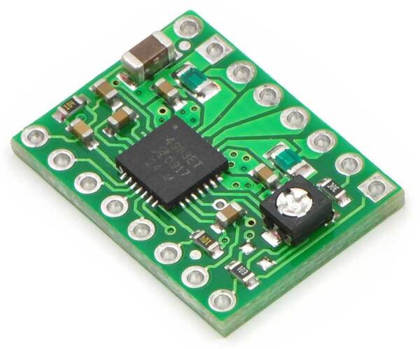
A happy solution presented itself yesterday. Pololu offers a breakout board equipped with an Allegro A4983 controller.
The A4983 is somewhat different than the A3977 that is standard in Reprap electronics in two ways. Foremost, the A4983 can handle a maximum current of only 2 amps instead of the A3977's 2.5. I don't find this compelling because in practice Repraps rarely require more than 1 amp in any case.
The winner for me is that the A4983 controller allows for microstepping down to 1/16 compared to the A3977's 1/8. While the A3977's microstepping is more than adequate for conventional Reprap machines I can use the extra resolution with the Delta Robot.
A happy solution presented itself yesterday. Pololu offers a breakout board equipped with an Allegro A4983 controller.
The A4983 is somewhat different than the A3977 that is standard in Reprap electronics in two ways. Foremost, the A4983 can handle a maximum current of only 2 amps instead of the A3977's 2.5. I don't find this compelling because in practice Repraps rarely require more than 1 amp in any case.
The winner for me is that the A4983 controller allows for microstepping down to 1/16 compared to the A3977's 1/8. While the A3977's microstepping is more than adequate for conventional Reprap machines I can use the extra resolution with the Delta Robot.
Sunday, January 31, 2010
Many useful little things...
Back in the late 1960s when I was very young and worked for IBM for a few years there was a magnetic tape that always lay beside the operator's console on the ancient IBM 360-40 computers labeled MULT. One day I worked up the temerity to ask the operator what it was and he said MULT stood for "many useful little things", viz, MULT. It was a compendium of utilities programmes that enabled the operator to maintain the old 360 and, given how reliable mainframe computers were in those days, was always kept very close at hand.
The projects that I've begun to undertake vis a vis Reprap reminded me of that old mag tape. Basically, I've been undertaking to explore technologies that might get the Reprap community into the next generation of Reprap machines. More to the point, I'm trying to crack some of the technical challenges posed by the Kartik M. Gada Personal Manufacturing Prize. Mind, I'm not looking to compete for the prize. The technical challenges, however, are very interesting.
Before the Gada Prize was announced, I was developing herringbone racks and pinions as a printable alternative to belts. Once the prize was announced, the 90% printed by volume and the 60 watt power limit specifications drew my interest. Prior to the prize announcement, I'd bought all the pieces to build up a heated bed for my Rapman 3.0 printer. It was obvious, however, that there was no way that a 3D printer with a heated bed was going to be possible using less than 60 watts.
At the time that I was thinking about all of this I was trying to develop a rail system to contain my herringbone rack so that I could use it to drive axes. I wanted to build a Delta Robot something along the lines that Festo had done.
The Festo Delta Robot uses lead screws in the three columns that seat the arms that move the extruder. I wanted to replace those with herringbone racks. I also wanted to make the columns printable. In that a usuable Delta 'bot is about a meter high, it was obvious that I wasn't going to be able to print a column in one piece. That put me face to face with the question of how to make a large piece out of a bunch of little pieces.
The conventional approach is to simply bolt the small pieces together. Frank Davies took this approach with his brilliant Sarrus Linkage positioning system.
Frank had avoided a lot of problems with printing larger parts by using relatively thin-walled, open structures. I shamelessly stole a lot of his techniques after having printed part of his Sarrus system. While thinking about that it occurred to me that you get relatively little warping if your part's biggest xy dimension is less than about 50 mm. Most of the parts I wanted to print had a cross section much smaller than that but were long and I needed them to be VERY accurate.
Then came the little epiphany. Why not rotate the long dimension to the vertical and leave the small cross-section on the xy print surface? Nophead {Chris Palmer} quite rightly pointed out that for a beam the extreme fibres on the upper and lower surfaces would be no stronger than the bond between two layers of printed plastic whereas if you printed the long dimension flat on the xy plane the bond between layers would only be subject to shear stress. In spite of that I began designing a columnar rail system for my herringbone racks and began printing it vertically, reasoning that a bending stresses would not be as severe in a column as in a beam.
After half a dozen false starts I finally got a design I liked. I rewrote the rack generation script for Art of Illusion so that it would put a flange on either side of the rack and then designed a cross-section that would seat racks on front and back sides. One of the racks would carry the drive pinion while the other would seat a pair of unpowered bogies to stabilise the positioning assembly.
Here you can see a printing of a 100 mm long pair of these columnar rails.
Note that printing vertically allows you to create hollow structures, something much more difficult to do with present technology if you print them on their side. Also note how much like an extruded plastic or aluminum section this columnar segment looks. That was intentional. If some enterprising small Chinese factory starts paying close attention, it may be that this sort of section can become a very cheap vitamin instead of something that Reprappers in well served market areas have to print. That cuts down replication time dramatically.
I'd originally designed the column elements to test whether the rack prints fit properly. They did.
Before you start thinking that I'm some sort of design wizard, let me say that it took me four tries to get the fit right. This sort of design thing is very hard work for me.
That accomplished I was beginning to design the connection between the columnar segments when it occurred to me that the rack prints already did that.
What is nice about this approach is that you can simply slide rack segments into the column until it is full. I found as a practical matter that the segments dovetailed very accurately with just a touch of very fine grit sandpaper to knock off tiny bits plastic flash on the ends.
Just looking at the system one immediately realises that the join between segments is not what you would call a particularly strong. That is where an old trick I learned in architectural and structural engineering design eons ago came into play, viz, post-tensioning. In construction concrete is well known for being able to resist huge compressive loads but can resist virtually no tensile loading at all. Plastic, the way I was printing it vertically, as Nophead rightly pointed out, doesn't have good tensile strength and will, given sufficient load, fail in bending. In that way it is very much like concrete.
In building in concrete post-tensioning allows you to overcome this problem. The method is quite simple. You cast your concrete structure leaving channels through it. After it has hardened {cured} you thread tendons through these channels and then use hydraulic jacks to put the tendons in tension. The tendons are connected to either end of the beam you are building by face plates. The tensioned tendons, usually made of either high strength steel rod or cable, compress the concrete beam strongly via the end plates to which they are attached. Any bending forces put on the beam thereafter have to overcome this compressive force on the concrete before the beam can fail. The method is very widely used.
I printed up some end plates and cut a piece of #8 studding {4.2 mm threaded rod} for the tendon.
Here you can see the end plate and tendon in place.
Finally, I point loaded the resulting post-tensioned structure with a 750 gram Mag-Lite. The 200 mm column section weighs about 45 grams of which the steel and fixings account for 12-15 grams.
No visible deflection was observed. This beam in this orientation is 18 mm deep, mind, and the top and bottom membranes are 1.75 mm thick ABS. I will use this same approach for both columns and beams in the Delta Robot I am designing.
I think that by deepening the beam to 24-30 mm you could probably replace Rapman's 12 mm milled steel guide rods {and probably Darwin/Mendel's ... I haven't checked the exact specification} with a post-tensioned, virtually entirely printed equivalent using about 6% of the steel {#8} as is presently used.
Keep in mind that the #8 studding tendon is massively overdesigned. I bought #8 simply because, for some odd reason, it cost about on-third as much as #4 {2.8 mm equivalent}. Using perfectly adequate #4 studding would bring that steel fraction down to 4%. Heavens, even #2 would do the job!
One issue with this kind of development is creep, the tendency of plastic under stress to deform over long time frames. It may be that we are simply not loading plastic to anywhere near the stress levels where this becomes a problem. It warrants a hard look, however. Unfortunately, the reference manuals on plastics creep are quite expensive, viz, hundreds of dollars and are rather spotty in the coverage of plastic types that they discuss.
The projects that I've begun to undertake vis a vis Reprap reminded me of that old mag tape. Basically, I've been undertaking to explore technologies that might get the Reprap community into the next generation of Reprap machines. More to the point, I'm trying to crack some of the technical challenges posed by the Kartik M. Gada Personal Manufacturing Prize. Mind, I'm not looking to compete for the prize. The technical challenges, however, are very interesting.
Before the Gada Prize was announced, I was developing herringbone racks and pinions as a printable alternative to belts. Once the prize was announced, the 90% printed by volume and the 60 watt power limit specifications drew my interest. Prior to the prize announcement, I'd bought all the pieces to build up a heated bed for my Rapman 3.0 printer. It was obvious, however, that there was no way that a 3D printer with a heated bed was going to be possible using less than 60 watts.
At the time that I was thinking about all of this I was trying to develop a rail system to contain my herringbone rack so that I could use it to drive axes. I wanted to build a Delta Robot something along the lines that Festo had done.
The Festo Delta Robot uses lead screws in the three columns that seat the arms that move the extruder. I wanted to replace those with herringbone racks. I also wanted to make the columns printable. In that a usuable Delta 'bot is about a meter high, it was obvious that I wasn't going to be able to print a column in one piece. That put me face to face with the question of how to make a large piece out of a bunch of little pieces.
The conventional approach is to simply bolt the small pieces together. Frank Davies took this approach with his brilliant Sarrus Linkage positioning system.
Frank had avoided a lot of problems with printing larger parts by using relatively thin-walled, open structures. I shamelessly stole a lot of his techniques after having printed part of his Sarrus system. While thinking about that it occurred to me that you get relatively little warping if your part's biggest xy dimension is less than about 50 mm. Most of the parts I wanted to print had a cross section much smaller than that but were long and I needed them to be VERY accurate.
Then came the little epiphany. Why not rotate the long dimension to the vertical and leave the small cross-section on the xy print surface? Nophead {Chris Palmer} quite rightly pointed out that for a beam the extreme fibres on the upper and lower surfaces would be no stronger than the bond between two layers of printed plastic whereas if you printed the long dimension flat on the xy plane the bond between layers would only be subject to shear stress. In spite of that I began designing a columnar rail system for my herringbone racks and began printing it vertically, reasoning that a bending stresses would not be as severe in a column as in a beam.
After half a dozen false starts I finally got a design I liked. I rewrote the rack generation script for Art of Illusion so that it would put a flange on either side of the rack and then designed a cross-section that would seat racks on front and back sides. One of the racks would carry the drive pinion while the other would seat a pair of unpowered bogies to stabilise the positioning assembly.
Here you can see a printing of a 100 mm long pair of these columnar rails.
Note that printing vertically allows you to create hollow structures, something much more difficult to do with present technology if you print them on their side. Also note how much like an extruded plastic or aluminum section this columnar segment looks. That was intentional. If some enterprising small Chinese factory starts paying close attention, it may be that this sort of section can become a very cheap vitamin instead of something that Reprappers in well served market areas have to print. That cuts down replication time dramatically.
I'd originally designed the column elements to test whether the rack prints fit properly. They did.
Before you start thinking that I'm some sort of design wizard, let me say that it took me four tries to get the fit right. This sort of design thing is very hard work for me.
That accomplished I was beginning to design the connection between the columnar segments when it occurred to me that the rack prints already did that.
What is nice about this approach is that you can simply slide rack segments into the column until it is full. I found as a practical matter that the segments dovetailed very accurately with just a touch of very fine grit sandpaper to knock off tiny bits plastic flash on the ends.
Just looking at the system one immediately realises that the join between segments is not what you would call a particularly strong. That is where an old trick I learned in architectural and structural engineering design eons ago came into play, viz, post-tensioning. In construction concrete is well known for being able to resist huge compressive loads but can resist virtually no tensile loading at all. Plastic, the way I was printing it vertically, as Nophead rightly pointed out, doesn't have good tensile strength and will, given sufficient load, fail in bending. In that way it is very much like concrete.
In building in concrete post-tensioning allows you to overcome this problem. The method is quite simple. You cast your concrete structure leaving channels through it. After it has hardened {cured} you thread tendons through these channels and then use hydraulic jacks to put the tendons in tension. The tendons are connected to either end of the beam you are building by face plates. The tensioned tendons, usually made of either high strength steel rod or cable, compress the concrete beam strongly via the end plates to which they are attached. Any bending forces put on the beam thereafter have to overcome this compressive force on the concrete before the beam can fail. The method is very widely used.
I printed up some end plates and cut a piece of #8 studding {4.2 mm threaded rod} for the tendon.
Here you can see the end plate and tendon in place.
Finally, I point loaded the resulting post-tensioned structure with a 750 gram Mag-Lite. The 200 mm column section weighs about 45 grams of which the steel and fixings account for 12-15 grams.
No visible deflection was observed. This beam in this orientation is 18 mm deep, mind, and the top and bottom membranes are 1.75 mm thick ABS. I will use this same approach for both columns and beams in the Delta Robot I am designing.
I think that by deepening the beam to 24-30 mm you could probably replace Rapman's 12 mm milled steel guide rods {and probably Darwin/Mendel's ... I haven't checked the exact specification} with a post-tensioned, virtually entirely printed equivalent using about 6% of the steel {#8} as is presently used.
Keep in mind that the #8 studding tendon is massively overdesigned. I bought #8 simply because, for some odd reason, it cost about on-third as much as #4 {2.8 mm equivalent}. Using perfectly adequate #4 studding would bring that steel fraction down to 4%. Heavens, even #2 would do the job!
One issue with this kind of development is creep, the tendency of plastic under stress to deform over long time frames. It may be that we are simply not loading plastic to anywhere near the stress levels where this becomes a problem. It warrants a hard look, however. Unfortunately, the reference manuals on plastics creep are quite expensive, viz, hundreds of dollars and are rather spotty in the coverage of plastic types that they discuss.
Monday, January 25, 2010
Getting there with herringbone rack and pinion
I finally hit a break in my day job and after sleeping the clock around beginning Friday afternoon was able to get back to my Reprap work. I'd been working with herringbone rack and pinion design and had begun writing Art of Illusion scripts to generate this kind of technology. I'd done most of the rack script a few weeks ago, but I needed to be able to design herringbone gears a bit more efficiently.
Finally, on Sunday the scripts for the racks and gears began to come together. After a considerable amount of feeling around I found that I could reliably print an 8 mm radius, 12 toothed gear. Connecting such a pinion directly to a 1.8 degree step NEMA 17 gives me a 0.25 mm/ step on the axis without microstepping. I then designed a 32 toothed gear which let me get that resolution down to 0.094 mm/step. You can see the layout here...
The NEMA 17 turns the 12 toothed pinion at the top of the picture. It turns the 32 toothed gear which shares an axle with a second 12 toothed pinion which engages the rack. It's simple, easy and quick to print and doesn't backlash if you apply just a slight bit of compression to the gear train. My next task is to design a printable axis assembly to house it. My goal is to get rid of the skateboard bearings, too.
The scripts are in a lot better shape, but they're still not really ready for prime time.
Thursday, January 14, 2010
A printable, high speed alternative to belts?
Years ago, I created AoI scripts to design involute profile gears and racks. Recently, I've been exploring the notion of using rack and pinion drives instead of belts. While it is relatively easy to design and print a rack and pinion gear set, conventional ones have a problem with lateral stability.
I soon found that I was buying far too many skateboard bearings to make up for this problem than was sensible.
A month or so ago, I ran across the idea of herringbone {double helical} racks and gears.
You don't hear too much about this kind of gear and rack mostly because it can't be machined with conventional hobbing machines. It can, however, be printed relatively easily. I found that I could coax my extant rack and gear scripts to produce such components.
I was at, however, pretty much the limit of what Art of Illusion could handle. By the time I converted an involute gear profile or a rack to a triangle mesh then extruded and did a few boolean ops on it even the improved power of AoI 2.8 was barely up to the job.
While I could typically make herringbone gears happen the racks were a real trial. This had a bit to do with the fact that a rack profile does some really strange things when you apply AoIs triangle mesh routine to it.
You could extrude that and only get webbing on the outside surfaces. As you can see, however, you get lots and lots of triangles from AoI. I soon found that I could not make herringbone racks with more than about 12 teeth. It was easy to see with a rack that you ought to be able to describe it with relatively few triangles, so I gritted my teeth and decided to go directly to a solid description.
Using the Platonic Solids script as a point of departure, I began to develop a herringbone rack script.
I finally got the whole thing going during lunch today.
I checked the resulting STL in Netfabb and determined that it was perfect.
I developed a 12 toothed 10 mm radius herringbone rack and pinion pair.
This configuration gives you about 0.3 mm/step when you attach a 1.8 degree stepper to it. Gear that down by a factor of 3 using another herringbone gear pair and you've got the 0.1 mm/step standard Reprap resolution.
Herringbone gears are pretty much naturally anti-backlash. They seat firmly, are quiet and have strong lateral resistance. They're printable and there is no reason whatsoever why you shouldn't be able to use them instead of a belt. I printed up a 130 mm rack and pinion set this evening.
The racks can also, since they are very thin, be printed in long lengths without warping. Using a 0.3 mm extruder orifice and printing at about 16 mm/sec I completed the rack in about an hour and twenty minutes and the gear in 45 minutes.
I've been able to make rack and pinion sets with gear finenesses of 24 teeth for a 10 mm radius. That's really pushing the envelope, though. It appears that 20 teeth for 10 mm radius is a practical limit.
I intend to clean up the rack script and write one for the herringbone gears now that I know that they work well. I will make the scripts available as soon as I have them cleaned up a bit.
This experience has brought home what I consider a very important point for me. We need to be looking for technologies that aren't necessarily cheap or usual in metals. Such components are dependent on purpose built milling machines. Our printers are much more flexible than that. We need to choose technologies to print with that in mind.
Friday update:
I queued up a 267 mm rack while I was working this morning. No warping.
Not bad.
Sunday, January 03, 2010
A note to my old friend, Hitech.
Think about buying or building your kid one of these. It's an open source 3D printer. I bought mine from BitsfromBytes in the UK for about $1,200, mostly because I was in a hurry. You can build your own for maybe a third of that.
You can either buy the controlling electronics off-the-shelf.
... or ... if you want to get your kids into electronics, you can build up your own like I do at times. I tend to use stripboard for circuitry. You can get stripboards cheap out of New Jersey.
I use DIP though-the-hole chips because I'm old and clumsy. Little fingers can handle them a lot easier than you can with surface mount chips and components. I put together a layout app for design.
That makes getting from concept to board a lot easier.
Once you have your 3D printer working you can get your kids going designing and building THINGS instead of sketching things on paper or on some 3D CAD program.
I think there is a lot of potential for getting kids used to thinking in terms of solid objects and how things go together. One of the immediate applications is for kids to design and build their own robots. Robots tend to be team efforts at the kid level largely because there are parts that are expensive to make because you either have to have a machine shop or access to one. With a 3D printer you can simply print the fiddly bits.
Monday, December 28, 2009
Printing Geneva Wheels
For some time I have been working on a magnet coil winder project. One of the things that I wanted was a tally counter to keep track of how much wire I was putting on the coil and another to keep track of how many turns that I made on my electromagnet spool.
For a long time I tried to simply tried to replicate a classic tally counter. Unfortunately, that design was optimized for the use of springs and disks and a pawl of spring steel. I wanted to do the whole thing in plastic, or as much in plastic I could, so I turned to the venerable Geneva Wheel to do the job.
Here, complements of Wikipedia, you can see how a Geneva wheel mechanism actually works.
I wrote a script in Visual Basic .NET 2008 to produce the outline of a ten step Geneva Wheel instead of the four step one shown in the Wikipedia graphic. I read a file generated from that script using a script in Art of Illusion and created a solid object of the outline.
From there I generated the resulting gcode using Skeinforge.

I will post the rest of the mechanism to this blog entry as I get it done.
For a long time I tried to simply tried to replicate a classic tally counter. Unfortunately, that design was optimized for the use of springs and disks and a pawl of spring steel. I wanted to do the whole thing in plastic, or as much in plastic I could, so I turned to the venerable Geneva Wheel to do the job.
Here, complements of Wikipedia, you can see how a Geneva wheel mechanism actually works.
I wrote a script in Visual Basic .NET 2008 to produce the outline of a ten step Geneva Wheel instead of the four step one shown in the Wikipedia graphic. I read a file generated from that script using a script in Art of Illusion and created a solid object of the outline.
From there I generated the resulting gcode using Skeinforge.
I will post the rest of the mechanism to this blog entry as I get it done.
Subscribe to:
Posts (Atom)