Monday, November 30, 2009

First Rapman raft with Slice and Dice

I got things hot-wired together to produce a gcode file for the first layer of the raft.


It looks a little rough, mostly because I am not that comfortable with gcode yet.  It's a fitted raft as opposed to Skeinforge's largest dimensions plus two times the skirt width method for creating them, however.

It's a start.

Oh yeah, still no resets.

Sunday, November 29, 2009

Patching slices and building rafts


Slice and Dice works a bit differently than Skeinforge in places.  To demonstrate a few of the differences, let me use the half-dome that I processed in Skeinforge a few days ago as a point of departure.  This is what it looked like in AoI.


Fixing flawed slices

Slice and Dice cuts the half-dome's STL file in much the same way that Skeinforge does.  Here is an example slice.


When I do image processing, however, having a tight loop around the sliced area is mandatory.  If there are any flaws in the loop, flooding fills the interior of the slice as well as the exterior.


Where Slice and Dice starts getting different to Skeinforge is that when this sort of thing happens, you just pull the relevant image into something like Windows Paint and see if you can find the hole(s).  The hole in this one is very small, but very easy to find.


It was a matter of a moment to plug the leak using Paint.


I then just reflood that slice and it now works perfectly.


Building the raft

I had run into trouble with the Skeinforge raft.  If you have a long object and rotate it 45 degrees to take advantage of the diagonal  Skeinforge still designs a raft using the largest and smallest x and y coordinates.  That wastes a lot of filament and print time.  As well, when you have a non-rectilinear object such as my half-dome you still get more raft than you really need.


I had two problems to address.  First, I had to have a footprint which included overhangs.  I achieved this by the simple expedient of just summing the flooded slices which yielded a composite.


I then created the skirt by wrapping half millimeter bands around the footprint till I had the skirt I wanted {15 mm}.


I won't illustrate, visually, for generating the print roads for the extruder given the area to be printed.  You can see that in a previous blog entry.  The resulting roads, however, are somewhat different than what Skeinforge generates.  Slice and Dice treats the raft as just another slice and uses a perimeter and infill arrangement.  Here you see the first layer.


I am trying out the notion that having perimeter support for the raft might let it need a smaller footprint than Skeinforge's openwork raft arrangement.

Slicing and dicing with image processing


Originally posted in ATechnicalFix.com on August 9th, 2009

In which your narrator rebuilds Tommelise’s Slice and Dice app.

Some years ago with Tommelise 1.0, I built a routine to slice STL files and lay out tracks for printing plastic on each slice. It worked reasonably well. After that, I completely rebuilt the app to do milling instead. As well, I developed routines to do milling of printed circuit boards. A few months ago, I resolved to go ahead and develop Tommelise 3.0. This entailed a completely new controller design centered around the I2C bus. That’s pretty much done. I hit a dry point in my creativity and spent a few months developing a stripboard design routine which I recently published.

Since then, it has become obvious from the complaints of several other Reprap team members that the open source Art of Illusion 3D modeling package leaves a bit to be desired. I’ve always had good luck with AoI and have, until recently. been puzzled by the bad press it’s got. Nophead (Chris Palmer) in Manchester has been very critical of AoI. I always take Nopheads criticisms VERY seriously in that he is a very thorough person and doesn’t say negative things without considerable justice. Nophead and I did a cycle of parallel tests on AoI and discovered that you can run it in what are, for practical purposes, virtually identically configured PC’s and get either excellent performance (me) or miserable performance (Nophead). That wants some serious looking into by the people on the Art of Illusion team.

Mind, my experience with AoI hasn’t been without it’s frustrations, though nothing as bad as what Nophead reports. The major problem I had was with my own slicing routine. If AoI sent over a STL which was not Euler Valid, that is, with all of the triangles making up the surface pointing outwards, my slicing routine couldget a little unstable. Not to put too fine a point on it, that means that I’d get a very bizarrely printed layer.

I’ve liked to boast that I use a grid approach to dealing with slicing and dicing as opposed to the geometric approach that Adrian’s august background in 3D graphics lets him do. Grid processing is slower but all the same tends to result in much simpler and easier to maintain, by me anyway, code. The problem historically with my slice and dice routine is that it wasn’t quite completely grid oriented, but rather a “neither fish nor fowl nor good red beef” mix of grid and geometric techniques. I decided to fix that.

Doing the Slice

Using a grid is very simple. Basically, I just create a picture box big enough to hold the object’s xy dimensions and set the pixel size to the step size of the xy steppers. I then take a slice of the STL and map it onto the picture.

The lines making up the slice are automatically represented as pixels on the picturebox, so which way a vector is pointing and other minutae that give geometrical approaches headaches simply aren’t there.

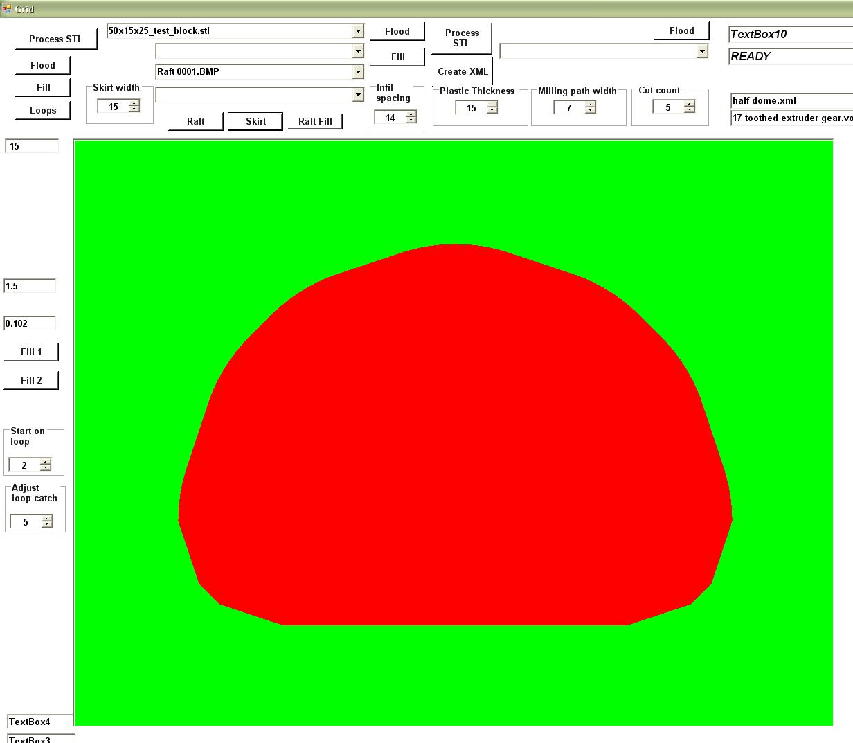
You get something that looks like this…


Once you have your slice boundaries laid down you have to fill in the parts of the slice which are to be printed with plastic. Those areas are shown in red while empty places are shown in green.

The routine that does this is very, very short and very robust. You can see the process underway here…


…and complete here…


Once you have your slice painted onto your picture box you need to figure out where the roads your extruder is going to have to travel. This is accomplished by…

  • Painting a border around the inside of the perimeter of the slice that is one-half of the width of your extrusion road less one step resolution distance {done in blue}
  • Paint a white midline for the extrusion road on the inside of that blue stripe
  • Paint another blue stripe next to that which is one-half of the width of your extrusion road less one step resolution distance plus the distance to the ends of your infill roads.
  • Paint your infill road midlines

You can see this process underway here…


Once that process is done, you simply wash the colours away leaving only the pixels delineating the printroads. You see that process underway here…


Once that is done, you collect the roads. I paint each road a different colour so that I can make sure that there are no breaks. That process is underway here.


Ultimately, I am going to do this in two steps, the first to collect the perimeter roads and the second to collect the infill roads. That is only a bookkeeping issue.

The only part of the code I have not yet written goes through and arranges a print order which minimizes the distance that the print head must move between infill roads so that the Tommelise 3.0 print head does not spend a lot of time moving around while not printing a layer. I’ve written that sort of code for the old slice and dice app, so I don’t see it as being any big deal.

Years ago in China, I had the unique opportunity to spend an evening with Benoit Mandelbrot, who brought the fractal into the general public awareness. He related a story that, I think, has some important things to say for Reprap design. When he originally went to work for IBM he was given the task of working with a particular device that was very sensitive to electrical noise. Any time repairmen in the building used an electrical drill the device malfunctioned. His supervisors at IBM wanted Benoit to track down and eliminate the sources of the noise. Benoit, being the sort of man he is, disagreed and insisted that there would always be noise caused by one thing or another and it would far better to figure out how to somehow shield the device from such noise or somehow make the circuitry itself in the device noise tolerant.

That is what I am trying to achieve with this new incarnation of Slice and Dice.  It seems to me that we are going to be confronted with how to process bad STL files for a long time, given the state of the art with open source 3D modeling packages' boolean ops routines.  The flooding process that I use in Slice and Dice shows you very quickly where such faults manifest in a particular slice.  Rather than having to fall back on fooling with code, a Slice and Dice user can simply use something like Windows Paint or Photoship to fix the the and image and then go on from there.

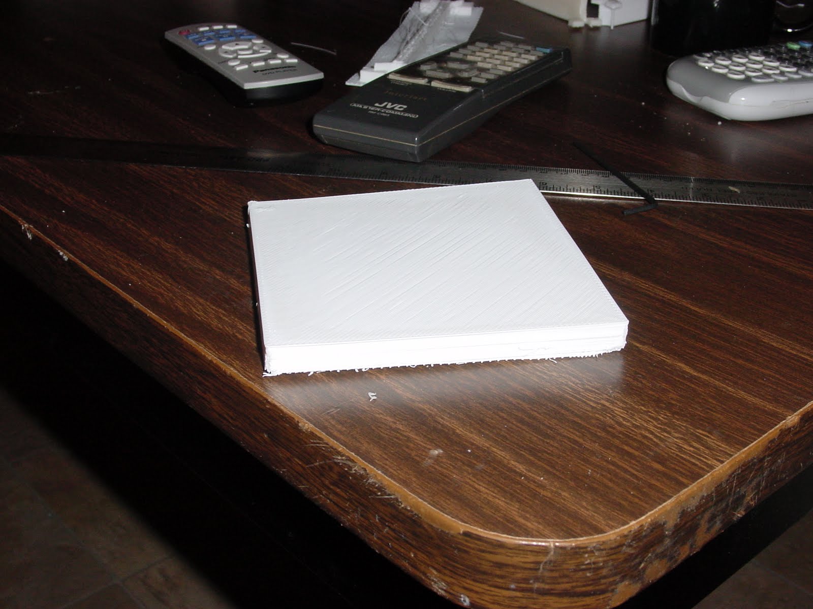
Just so you are reassured that this is only robust for an over simple case…


Keeping that in mind, I’ve arranged to save the developing slices as images. This requires substantial hard disk space, but disk space is a trivial expense these days. Doing that gives me a number of very powerful capabilities.

I can review a print job visually, slice by slice and assure myself that there are no problems therein.
Should there be problems that can’t easily be cured by working with the 3D modeling app {AoI, for instance}, I can easily just pull the marred images into something like Photoshop and fix them, then reprocess the road building.

I haven’t got a full tool-path from AoI to Tommelise 3.0 yet, but it is looking very strong. It would be a very small matter to filter myslice and dice output into G-Code and use it in mainstream Reprap machines. I want to convince myself that I’ve really got something worthwhile before I suggest that sort of thing, though.

Monday, November 16, 2009

Exploring support material in Skeinforge


Skeinforge has the possibility of generating support materials for overhangs for single extruder Reprap 3D printers. I decided to see how it worked. To do that, I created a dome in Art of Illusion and then cut away half of it.


Running it through Skeinforge...


The print began well...


...and progressed...


It was obvious that the extruder head was spending more and more time on a progressively small area as the dome print progressed.


You can see as well that waiting for temperature exchanges to take effect was causing a great deal of extruder dribble.  I discovered that you can get a raft off of your polypropylene print board if you print the first layer of the raft at 225 C and the second at 230 C.

If you then drop the temperature of the layer between raft and dome to 205 C it is fairly easy to get the print off of the raft.  This had been a problem at higher print temperatures.  The dome itself was printed at 230 C and the support material at 205 C.  While Skeinforge estimated the print time of this half dome at an hour it didn't estimate the time temperature changes in the extruder would take.  Those added another 1-2 hours to the print time.


Support material separated easily from the half dome.


Looking closely at the support structure it was well consolidated.  That left me to wonder what would have happened had I printed the whole half-dome at 205 C.


I wonder as well if a bit of moving air would have retarded the melting at the top of the dome.


It would seem as well that programming in significant wait times between layers would have given me a finer print.

I have quite a few parameters to twiddle in coming days.

Making spares for Rapman


Yesterday, klaszlo, a member of the Rapman users' group wondered how he could get spares for the gear pair on the Rapman 3.0. For many of us, the whole point of Reprap machines is to print our own spares rather than tormenting Ian at BitsFromBytes every time we break something.

Did somebody already designed (ready to print) replacement gears for the extruder?
I think the gears are big enough, that we are able to print them out...


As it developed, nobody had. I wondered how hard an exercise it could be and decided to have a go at it.

I designed the gears as involute profile using a script I wrote some years ago for Art of Illusion rather than attempt to duplicate the spiky ones that come with the Rapman. The pair had a rather odd 14:17 ratio. That done I printed them out in HDPE.


As you can see, the dimensions and tooth counts are the same. In the 14 toothed gear I used depended on a friction fit with a flat side on the 4 mm stepper shaft rather than the grub screw arrangement used in the acrylic original.


I printed the raft base at 225 C and the second layer of the raft at 230 so that it would stick properly. I also printed the transition layer between the raft and gear at 215 C. I've not had any trouble getting the raft off of the polypropylene print surface. Getting the raft off of the printed part when the transition layer is 225 is nearly impossible, however. The 215 C setting made separating the gear from the raft barely possible. I will be trying lower temperatures to find a sweet spot that makes getting the raft detached workable without special tools being required.


This would probably work better with an 0.3 mm extruder head. I've ordered one, but I am not sure yet how much drama will be entailed in getting it to work with Skeinforge.

That exercise got me to wondering how much drama would be involved in getting some of the other Rapman parts printed. Looking at the parts, the extruder seemed to have the most massive pieces. AK47 commented yesterday that the 125x125x10 mm text block that I printed was possibly the largest single piece printed so far. The block is big, but I don't know if it sets any sort of record. Certainly, Mendel is bound to have pieces requiring more than 59 cm^3 of plastic.

I grabbed the biggest part of the Rapman extruder and did a tracing of it to get an idea of its dimensions. Here is what it looks like.


At 120x174 mm it is going to be a bit bigger than the test block we did yesterday and, once we put 15 mm of raft perimeter around it, it will pretty much occupy the whole of Rapman's print surface.

Addendum:

Bogdan suggested that I up the Infill Overlap Ratio from 0.3 to 0.7 to get a better fill into the teeth of the gear.


It does help. You can see the pair with the 0.7 infill overlap at the top.

Sunday, November 15, 2009

Bogdan's acid test


Bogdan suggested that we give the method an acid test and print a 125x125x10 block. I made up a test block in Art of Illusion and gave it a try. I ran the STL file through Skeinforge.


  • object: cube {125x125x10 mm}
  • printer: Rapman 3.0
  • firmware version: 1.0.6
  • slice and dice app: Skeinforge, 2009-10-31 build
  • material: HDPE {no additives}
  • print speed: 16 mm/sec
  • extrusion speed: 65 rpm
  • fill: 40% using hexagonal pattern
  • raft temperature {first layer}: 225 C
  • raft temperature {second layer}: 230 C
  • first layer temperature: 225 C
  • beam print temperature: 230 C
  • lab temperature: 18.3 C
  • lab humidity: 50%
  • raft perimeter width: 12 mm
  • beam dimensions: 5x20x180 mm
  • print time: ~360 minutes
  • print material ~53 cm^3
  • bowing: 2-2.5 mm over one diagonal {175-180 mm}
I used "L" shaped tension pads. Here you can see the raft printed and the transition layer for the block being laid down.


Enrique characterises this as a "hexagonal" fill for reasons that I do not fully understand.


All the same, in the right light the patterns his fill option makes are ravishing.


After about five hours the Rapman began to print the top on the block.

Bogdan's acid test 01 from Forrest Higgs on Vimeo.


And then it was done.


I didn't see the small amount of separation that had occurred across one diagonal until after I began to look closely at the pictures.


Looking back at the fill pattern what had happened is that the fill created a series of diagonal beams in the block which concentrated tensile stress along that diagonal


A similar shape is encountered in hyperbolic parabaloid roofs where beams are laid parallel to the perimeter boundary of the roof as in this illustration.


The difference was in our case the beams were laid on a diagonal.

The distortion along the diagonal amounted to about 2-2.5 mm over its 170 mm length. I suspect that I can cure this problem by using a larger tension pad. In the longer run, though, we've got to get a proper hexagonal fill instead of this pretty, but
anisotropic pattern that we currently have.

I can't get over how nicely the polypropylene printing surface for HDPE that Bogdan suggested works. I took a short videoclip to show you just how easy it is to get the object off of the print surface.

Bogdan's acid test 02 from Forrest Higgs on Vimeo.


Please pardon my elbow.

There was no distortion along the perimeter, only along the one diagonal.


More printing large objects with HDPE

After I achieved a 145x5x20 mm beam in HDPE, I decided to go for the limits of what my Rapman 3.0 could achieve. Rapman 3.0 has a printing area of about 200x200 mm. My thought was that if I rotated my beam around the z-axis by 45 degrees I ought to be able to push my largest dimension out to 280 mm or so.

If I were printing a line that would be true. Unfortunately, by the time I took the width of the raft that was necessary to keep the beam tacked down during printing was taken into account, I was only able to achieve a touch less than 180 mm, a length that was about the same as I could have managed if I'd printed the beam either along the x or y axis.


If you look at the tension pads you can see that they began to separate just as the print finished. This put about 1-1.5 mm of bowing into the beam over its length.

The printing parameters for the print were:
  • printer: Rapman 3.0
  • firmware version: 1.0.6
  • slice and dice app: Skeinforge, 2009-10-31 build
  • material: HDPE {no additives}
  • print speed: 16 mm/sec
  • extrusion speed: 65 rpm
  • fill: 40% using hexagonal pattern
  • raft temperature: 225 C
  • first layer temperature: 225 C
  • beam print temperature: 230 C
  • lab temperature: 18.3 C
  • lab humidity: 50%
  • raft perimeter width: 12 mm
  • beam dimensions: 5x20x180 mm
  • print time: ~100 minutes
  • bowing: 1-1.5 mm over length

I am going to attempt this print again with larger tension pads to see if I can get rid of the bowing observed in this print.