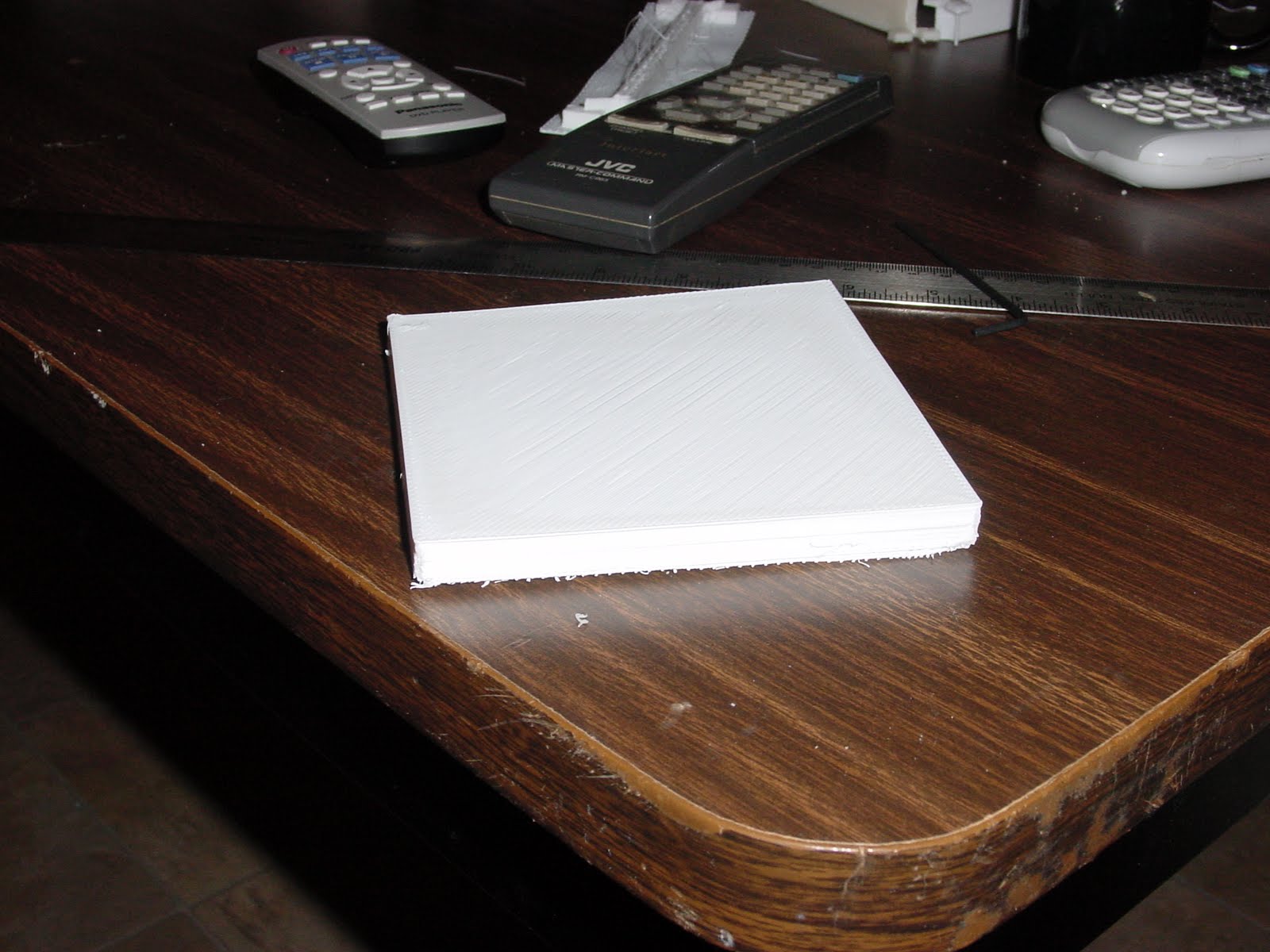
Bogdan suggested that we give the method an acid test and print a 125x125x10 block. I made up a test block in Art of Illusion and gave it a try. I ran the STL file through Skeinforge.

- object: cube {125x125x10 mm}
- printer: Rapman 3.0
- firmware version: 1.0.6
- slice and dice app: Skeinforge, 2009-10-31 build
- material: HDPE {no additives}
- print speed: 16 mm/sec
- extrusion speed: 65 rpm
- fill: 40% using hexagonal pattern
- raft temperature {first layer}: 225 C
- raft temperature {second layer}: 230 C
- first layer temperature: 225 C
- beam print temperature: 230 C
- lab temperature: 18.3 C
- lab humidity: 50%
- raft perimeter width: 12 mm
- beam dimensions: 5x20x180 mm
- print time: ~360 minutes
- print material ~53 cm^3
- bowing: 2-2.5 mm over one diagonal {175-180 mm}
I used "L" shaped tension pads. Here you can see the raft printed and the transition layer for the block being laid down.


Enrique characterises this as a "hexagonal" fill for reasons that I do not fully understand.

All the same, in the right light the patterns his fill option makes are ravishing.


After about five hours the Rapman began to print the top on the block.
Bogdan's acid test 01 from Forrest Higgs on Vimeo.


And then it was done.

I didn't see the small amount of separation that had occurred across one diagonal until after I began to look closely at the pictures.

Looking back at the fill pattern what had happened is that the fill created a series of diagonal beams in the block which concentrated tensile stress along that diagonal

A similar shape is encountered in hyperbolic parabaloid roofs where beams are laid parallel to the perimeter boundary of the roof as in this illustration.

The difference was in our case the beams were laid on a diagonal.
The distortion along the diagonal amounted to about 2-2.5 mm over its 170 mm length. I suspect that I can cure this problem by using a larger tension pad. In the longer run, though, we've got to get a proper hexagonal fill instead of this pretty, but anisotropic pattern that we currently have.
I can't get over how nicely the polypropylene printing surface for HDPE that Bogdan suggested works. I took a short videoclip to show you just how easy it is to get the object off of the print surface.
Please pardon my elbow.
There was no distortion along the perimeter, only along the one diagonal.

Bogdan's acid test 02 from Forrest Higgs on Vimeo.
Please pardon my elbow.
There was no distortion along the perimeter, only along the one diagonal.
25 comments:
I think you must have hit a bug there. I have seen people print heaxgonal infill that looked just like a honeycomb.
It all looks very promising though.
not a bug, just missconfiguration:
CRAFT/FILL/Infill ODD layer extra rotation: 90.0
seems he has 0.0 there
Wow that is the single largest piece I think I have seen printed to date.
There should be a list/tittle to go to the record holder of biggest monolithic print to date.
Or at least one per material.....
Great work guys.
Something wrong with the infill yes. Should be perfect hexagons each two layers.
With parts on that scale perhaps you could print a tiny RepRap capable of printing a Mendel. I.e. maybe the whole frame in one piece.
What's stopping us from printing the frame for a larger reprap machine in pieces and just bolting them together?
I still want to design and print that brushless, magnetless stepper we were talking about some weeks ago. I could use your help on that. If we can get steppers printed we take a big step towards a really high fraction of replicability. :-)
I have some initial designs for an all plastic frame if you want them.
I posted a piccy of the design ages ago. I think I called it "La Crate"
The frame is made from multiples of three components that are linked together with threaded Rod and short alignment dowels.
It could be made more efficient but I was thinking of a darwin compatible frame that the darwin top frame, drives and rails would attach to for ease of transition.
It features Skate bearing holding corner blocks for the upright drive members. And rebates on the sides of the cube to insert panels if needed.
It would need a bit more work on it but you are welcome to it if you want it.
BTW
An out-runner style brush-less DC Motor may be the easiest to kick off with.
ESC Controllers for these are available relatively inexpensively as RC components. (At least for a one of to experiment with)
The benefit of the out-runner style is there is little if not no risk of centrifugal force causing bits to fly off and it has higher torque characteristics.
I have a GWS one on my bench I have been studying.
They should also be relatively easy to build in such away that they become integral to threaded rod lead screws.
Thoughts for what they are worth.
Re "La Crate": Got a link?
Re: brushless DC motor: Does it have permanent magnets in it?
I have been having a rummage and can't find the original links etc.
Having just rebuilt my Linux laptop i am currently running up the virtual machine stuff. I did the crate design in Pro Desktop on XP in a virtual machine under linux, and it is in the backed up virtual machine.
Give me a little while to get it together and I will email/pm you the image.
I can tweak the design very quickly and easily in Pro Desktop if you need changes.
I'm not sure how G. Francia's hexagonal honeycombs worked, but maybe that's what Enrique was referring to...
Brushless DC Motors.
Yes they have permanent magnets in them.
It is easiest to think of them as a 3 phase stepper motor, that is'nt.
The phases are conventionally wired as per 3 phase motors ie Star or Delta.
Star is most common for RC Motors.
They have no brushes and the rotating part uses permanent magnets.
An in-runner type has the magnets in the spinning centre and the coils are stationary around the outside.
An out-runner type has the magnets around the spinning outside and the coils are stationary in the inside.
Commutation is achieved electronically via back EMF in sensor-less designs or by positional sensors, usually, but not exclusively hall effect sensing.
Their power to weight/size ratios and max RPM ratings are something to behold.
Their construction is correspondingly simple. Certainly more so that Brushed Motors.
The wikipedia entry on BLDC's (Brush-less DC Motors) is certainly worth a look at.
The permanent magnets are the problem. China controls 97% of the market for both the rare earths used in and the production of permanent magnets. I wouldn't worry about that except that they've decided to begin restrict exports of these materials to manufacturers outside of China in the past several years.
I really, really don't like anybody getting a monopoly position on critical technology, so I think we ought to design around the bottleneck.
Thats awkward.
It looks like you are stuck with brushed motoring then. Unless you want to try minature induction motoring.
Sounds like it could be fun.
I understand your view point on monopolies, The escalating price of copper though leaves you stuck between a rock and a hard place.
http://science.slashdot.org/story/09/09/08/2119201/China-Considering-Cuts-In-Rare-Earth-Metal-Exports?from=rss&utm_source=feedburner&utm_medium=feed&utm_campaign=Feed:+slashdot/eqWf+(Slashdot:+Slashdot)
An interesting article.
There are more permanent magnets than rare earth types.
Ferrite (Iron Oxide) magnets are probably good enough for our needs and can be sourced outside China.
A note on economic warfare.
Check Out
http://en.wikipedia.org/wiki/CoCom
and
http://en.wikipedia.org/wiki/Wassenaar_Arrangement
China appears to be rather absent from the list of countries that have free(er) trade.
It all smacks a little of "People in glass houses", Quid Pro Quo, Pot Calling Kettle black etc etc.
Makes me glad to ignore political ideology and deal with technical reality. Even if doing so may make me unpopular.
The other problem is that a magnetizer to make permanent magnets is a big, expensive piece of equipment that requires heavy currents.
I agree this makes it preferable to buy them ready magnetized.
http://e-magnetsuk.com/magnet_products/ferrite_magnets/
http://www.magnets2buy.com/acatalog/ferrite-magnets.html
http://en.wikipedia.org/wiki/Ferrite_%28magnet%29
Oh I guess there is also the pre rare earth magnet type Alnico, too.
http://en.wikipedia.org/wiki/Alnico
Yeah, but by the time you've bought the permanent magnets necessary to build a printable stepper retail you have lost any economic advantage to printing it over just buying it from the Chinese.
A good point indeed.
Always supposing that the Chinese supplied motors do not contain rare earth permanent magnets......
In which case there may well have to be Chinese suppliers of ferrite and alnico magnets that are perhaps competitively priced.
Alternatively you may actually really want to try the induction motor design just for fun and the challenge of seeing if it can be done.
Using iron oxide powders as fillers in polymers. I think is something we have touched on before as a way to make magnetic circuits that are potentially printable/mold-able.
Yeah, but then you've got to magnetize 'em. :-/
I get the feeling we are confusing two distinct threads of discussion here. Probably my fault for putting them both in one.
The threads..
Discusion 1. Whether there are permanent magnets available retail from somewhere other than china that can be used to make motors featuring permanent magnet motors of some type or other.
Discusion 2. making magnetic circuits for inductive motors etc.
The differences between the materials and applications......
Discussion 1 is the use of Hard Ferrite's and or Alnico. ie Non-rare earth materials as Permanent magnets. Yes you can manufacture these but as you quite rightly observed you need powerful electromagnets to magnetise them enough for them to stay magnetized. Ergo buy them already done they are readily available.
Discussion 2 is the use of Soft Ferrite's as the magnetic field focusing or channeling components in inductive machinery. ie transformer cores and motor rotor/stators (Take a look at choke inductors, pot cores and switch mode transformers (ie Ferox Cubes)).
These materials are difficult if not impossible to magnetize permanently and will readily allow the direction of magnetic flux to be reversed whilst channeling or focusing it. Note they exhibit low hysteresis where as metals used in magnetic circuits have higher hysteresis.
I guess it helps to think of magnetisim as being a circular flow of force. It flows between oposite poles. In a similar way it helps to think of electricity as being a circular flow of force. It flows between the poles or terminals, conventionally + to -. (Actual is the other way around)
If you make interlocked rings of your fore fingers and thumbs you get the relationship of related electrical and magnetic circuits. Each ring is a the flow and cross section of that is going off. (It is in reality a different way of looking at or using flemings right hand rule)
Given the concept of a magnetic circuit that is analogous to an electrical circuit (In electrical perhaps Copper is your conductor, in magnetic iron is the conductor) it becomes easier to understand their relation ships and how to manipulate them as mechanical components.
OK Discusion 1 and 2 collide a bit here.
If you make a magnetic circuit out of soft ferite without adding in a magnetizing force there is no magnetic field other than background noise.
If you make an electrical circuit out of copper without an Electro Motive Force (EMF) there is no electrical filed other than background noise.
Add a force to either and it will induce or create a counter force in the other. I guess this is realy nothing new to any of us.
Your motor design relies on the fact that you try to add both forces at the same time in such a way that they react and give heat/motion as a by product.
Whether you add it all electricaly or some of it through permanent magnetism. The fields of force still need channeling or guiding.
In transformer, motor and generator design air gaps are very wasteful of force as are incomplete circuits. Air is a conductor of magnetic force but a very poor one. I guess it is arguably an even poorer conductor of EM force.
I apologize if this long ramble has told you a lot of what you already know or has added more mud to the waters.
Post a Comment