Back at the beginning of 2006, before there was even a Darwin, eD Sells at the University of Bath was designing Darwin's predecessor, ARNIE. Confronting the problem of designing a z-axis, eD adapted the kinematics that were used on old wire cable parallel bars found on drafting tables.

eD adapted this technology in 3 dimensions to allow a single stepper motor to raise and lower ARNIE's print table.

Having trained as an architect before the Great Flood, I immediately fell in love the idea and adapted it to my failed Godzilla Repstrap design.

eD encountered no end of trouble with the cabling idea and eventually abandoned it for an approach which used four pieces of studding {threaded rod}.
It tends to be forgotten but the first fully operational Reprap machine at Bath was ARNIE, not Darwin. Indeed, Bath's traditional whiskey shot glass, the second one printed after Vik Olliver's in New Zealand, was printed on ARNIE. This approach was refined in Darwin.

Rapman, a Darwin derivative, was put into serial production by Bits from Bytes and is still selling quite well, today.

This z-axis approach does have its problems, though. Studding is most definitely NOT a proper lead screw. When you undertake to use four pieces of studding to raise a 3D printer's print table, the tendency of studding to be not quite straight plus the fact that you are using four pieces of not quite straight studding can lead to some unpleasant consequences. Here is an extreme example of what can happen.

If you expand the pic, you can see a nasty juddering of layers taking place. Here is a more usual example of the effect.

This is an extreme closeup with the light accentuating the effect. The object is quite smooth to the touch. The effect is still there, though. Here is a more usual picture showing the effect.
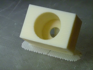
If you expand the pic you can see a regular pulse peaking at every seventh layer. This varies depending on how you adjust your machine and how straight your studding rods are. The closer the alignment, the better your print quality.
Now Bits from Bytes set out to solve this problem in their out-of-the-box BfB 3000 printer. They used a single proper lead screw to drive a cantilevered print table.

Both the Ultimaker and Makerbot's Thingomatic use the same approach.
Recently, when I decided to kaizen the old Darwin design, I decided to see what I could do about the z-axis situation. I didn't like the cantilevered print table approach and I did not want to simply duplicate the 4 studding solution originally used. That got me to thinking about the old cabling approach that eD had used back in 2006. The problem with it seemed to be applying force to the cable to move the print table. eD tried to use a friction wheel and eventually gave it up.
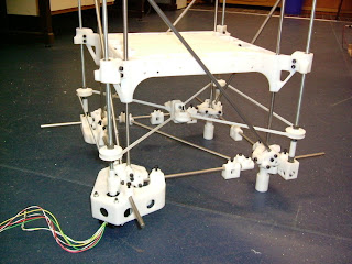
It occurred to me that it might be reasonable to use a single studding lead screw to apply force to the cabling. Lead screws can apply LOTS of force. So why not just attach one to the cable at a convenient point and be off?
I am in the process of doing just that.

I have circled the lead screw's thrust collar, the cabling turnbuckle and a linear bearing. Those three elements will be connected and a NEMA 23 stepper used to drive the cabling to raise and lower the print table.

Here you can see a detail of the cabling scheme associated with a pair of linear bearings on a vertical shaft. I have got to design a connector between the cable, the linear bearings and a corner of the print table. Hopefully, this approach will let me get a smoother z-axis operation without the juddering so characteristic of the Darwin design.

eD adapted this technology in 3 dimensions to allow a single stepper motor to raise and lower ARNIE's print table.

Having trained as an architect before the Great Flood, I immediately fell in love the idea and adapted it to my failed Godzilla Repstrap design.

eD encountered no end of trouble with the cabling idea and eventually abandoned it for an approach which used four pieces of studding {threaded rod}.

It tends to be forgotten but the first fully operational Reprap machine at Bath was ARNIE, not Darwin. Indeed, Bath's traditional whiskey shot glass, the second one printed after Vik Olliver's in New Zealand, was printed on ARNIE. This approach was refined in Darwin.

Rapman, a Darwin derivative, was put into serial production by Bits from Bytes and is still selling quite well, today.

This z-axis approach does have its problems, though. Studding is most definitely NOT a proper lead screw. When you undertake to use four pieces of studding to raise a 3D printer's print table, the tendency of studding to be not quite straight plus the fact that you are using four pieces of not quite straight studding can lead to some unpleasant consequences. Here is an extreme example of what can happen.

If you expand the pic, you can see a nasty juddering of layers taking place. Here is a more usual example of the effect.

This is an extreme closeup with the light accentuating the effect. The object is quite smooth to the touch. The effect is still there, though. Here is a more usual picture showing the effect.

If you expand the pic you can see a regular pulse peaking at every seventh layer. This varies depending on how you adjust your machine and how straight your studding rods are. The closer the alignment, the better your print quality.
Now Bits from Bytes set out to solve this problem in their out-of-the-box BfB 3000 printer. They used a single proper lead screw to drive a cantilevered print table.

Both the Ultimaker and Makerbot's Thingomatic use the same approach.
Recently, when I decided to kaizen the old Darwin design, I decided to see what I could do about the z-axis situation. I didn't like the cantilevered print table approach and I did not want to simply duplicate the 4 studding solution originally used. That got me to thinking about the old cabling approach that eD had used back in 2006. The problem with it seemed to be applying force to the cable to move the print table. eD tried to use a friction wheel and eventually gave it up.
It occurred to me that it might be reasonable to use a single studding lead screw to apply force to the cabling. Lead screws can apply LOTS of force. So why not just attach one to the cable at a convenient point and be off?
I am in the process of doing just that.

I have circled the lead screw's thrust collar, the cabling turnbuckle and a linear bearing. Those three elements will be connected and a NEMA 23 stepper used to drive the cabling to raise and lower the print table.

Here you can see a detail of the cabling scheme associated with a pair of linear bearings on a vertical shaft. I have got to design a connector between the cable, the linear bearings and a corner of the print table. Hopefully, this approach will let me get a smoother z-axis operation without the juddering so characteristic of the Darwin design.
12 comments:
very interesting timing! i am just printing out my new bed holders which are designed to eliminate wobble altogether, no matter how warped the rod.
--chylld
@Chylld Wonderful! It's great to have another way to solve the problem. When will you be publishing? :-)
I like it. I've been working on an aluminum frame with cable driven xy axii ala ultimaker.
http://dl.dropbox.com/u/4861696/Aluminum%20CrateStrap.png
I thought about replacing the x and y axes with cabling, but decided to test the technology on just the z-axis for this development round. That's what kaizen is about, after all. :-)
Hi, I'm enjoying following your build. I recently read this thread in the reprap forums:
http://forums.reprap.org/read.php?1,36928,37803#msg-37803
which had some useful info, and this picture of an old flatbed plotter:
http://forums.reprap.org/file.php?1,file=2053,filename=Gould-XY-1.jpg
For your application, an alternative might be to have two opposite sides with such an X configuration, connected by a rod with a fixed pulley at each end driven by the motor. This would be like a 3D version of a drafting table. The tensioner could be on a diagonal, as at the moment it looks like this might limit the Z axis movement?
I've been playing with an idea to use the fixed structural rods as leadscrews. The idea is to put belt pulleys around the leadscrew nuts, mount a motor to the print bed, and use a belt to turn the nuts to move the bed.
The bed would sit on thrust bearings, which in turn sit on the pulleys with embedded nuts. This would prevent warping of the leadscrew from causing wobble because the leadscrew doesn't turn. You would just have to ensure that the nut is in the middle of the bearing and the Z movement would be perfectly straight with a significantly simplified frame.
@whosawhatsis I've considered doing that on several occasions. The problem I've always run into is the nature of the joint between the thrust collar {your rotating nut} an the print table. The complexity of that has always finally discouraged me from proceeding. :-(
I was thinking about that. The assembly should be light enough that you can get away with using regular roller bearings instead of real thrust bearings. The bottom could be a cylindrical section with a hexagonal hole to capture the nut. The top of this section forms a guard on the belt pulley, which is a narrower toothed section just above the nut. Above that, it widens again at 45 degrees (for printing purposes) for the other guard, then narrows again to form a lip for the bearing to press against, and the final section fits tightly inside the bearing. The corners of the platform would just need holes to seat the bearings inside and a motor mount to drive the belt run around them. This should be pretty stiff as long as your bearings are held tightly and are wider than the height of the pulley a assemblies, but you could add a second nut on the top for anti-backlash purposes and to steady the platform (perhaps just on one or two of them, to avoid increasing the friction too much).
This would need large bearings, with an inner diameter at least, say, 5mm larger than the rod diameter, so 608s won't do. Then again, this is getting into the size that is ideal for printed bearings, and a thrust bearing would probably be easier to print and assemble than a roller bearing.
I don't know that a printed bearing would be appropriate for something like you propose. You'd need better accuracy, I'd think.
How about the bearings for a bicycle's handlebars & front fork? Those are available everywhere, and I think there are a few particularly common sizes.
I've been thinking about a similar system, except that the cable loops would extend beyond the machine using bowden cable sheaths.
This would allow for the drive mechanisms to be external to the printer body and so reduce the vibrations, potentially resulting in fewer movement errors. Furthermore, without the need to support motors and drive mechanisms, the structural elements could become simpler. We can already do this with the extruder.
All the axis drive mechanisms could be in a separate box along with the electronics. As this is independent from the printer, the arrangement of the printer would be irrelevant to the drive mechanism.
Providing the cabling remains the method of transferring the movement, the same drive box could be used for machines different in either arrangement (darwin, huxley etc.) or function (z cable could raise and lower 2 platforms together for powder based printers). Essentially whilst the path of the cable may change, the drive mechanism and electronics could remain the same.
Interesting concept. :-)
Post a Comment