Wednesday, August 25, 2010

Designing with a Reprap machine in the loop


In which your narrator celebrates a return to craftsmanship made possible with the addition of a Reprap printer into the design process.


In the five years I've been on Reprap team I think that possibly the most terrifying and depressing transition of the many I've made during that time was actually having a 3D printer on my worktable and having to face up to turning some of my pipe dreams into physical realities.

Let me tell you, it's a lot easier to dream up something than to actually cobble it together and get it working.

To begin with I had discovered that thin-walled prints tend to be quite strong, properly designed, and don't have nearly the trouble with warping that we've had with large, filled objects.

For a project I wanted to create an animatronic hand for a telepresence robot project I've wanted to undertake for several years now. If you go out to and buy one you're looking at anywhere from $5-50K for one hand. I haven't got that kind of money so I dug around on the internet till I found a guy in Indonesia who'd made one for $300 in parts.


Andreas Maryanto's  approach is both brilliant and cheap.  I used his project as a starting point and was able to use his blueprints for getting proportions and sizes right.

 I was also impressed with the Meka Robotics hand design.


Meka's hand was expensive, but had several interesting points.  It was self contained and used elastic bands to return the hand to an opened position.  I liked that.

I started small, with a fingertip.  Actually, half of a fingertip.  I did the design with Art of Illusion 2.8.  AoI has always been about the easiest to learn, free 3D CAD app around.  With the introduction of version 2.8 the problems with the boolean operators have been largely solved.


While AoI 2.8 will, occasionally, create a flawed STL file, these can be easily repaired in the free Netfabb Basic app.  The combination of Art of Illusion and the free Netfabb app, now available on the cloud as well, makes for an extremely powerful combination.

I wanted the joint between phalanges in the finger to be integral with the print, that is, not requiring any additional hardware. I printed and worked with the finger tip for quite some time.


Eventually, after a few dozen prints and redesigns, I got it to do what I wanted.


After that, the rest of the finger came together rather easily.


So, I had the joints right, but how to integrate the actuating tendons was a puzzle.  Within a week or so I had a tentative solution.  I could incorporate slots in the phalanges of the finger to guide and protect the tendons.  This meant that I had to import the STL files for the parts back into AoI and carve out the slots to seat the tendons.  Here you can see the STL for the second phalange slotted.


After slotting the second, third and fourth phalange in AoI and reprinting them I had a tentative solution for flexing the finger.


At that time I used a single tendon running through guides along the top of the finger.  That was later to change.


I quickly explored using servos very much like the ones Andreas had used.


...and just as quickly rejected them as overspecialised and too bulky for use in my hand.  From there I went on to creating my own servos from scratch using gearmotors and potentiomenters driven by a micro controller.

Once I'd settled on a gearmotor that I had a supply of...


...it became a matter of designing a section of the actual hand and accommodating the gearmotor inside.


Notice that the design of this part is only aiming at holding the outline of the gearmotor and providing a recess for the finger.  The goal is to work out the seating of critical parts and getting the general shape of the part right before trying to accomplish more.


At that point, I needed two finger assemblies to get a feel for the clearances and volumetrics between finger ensembles.


Attention to the reel that would wind up the tendon that contracted the finger was the next step.  I'd decided by this time to use a Meka-style elastic band on the top of the finger to return it to the open position.

The reel was a tiny, finicky part, given the clearances in the hand section.  I printed two of them at a time to avoid having to do a lot of pausing for the reels to cool between printed layers.


That done, I needed to do a bit more work with the hand section.  First, I needed to seat the gear motor.  The hand segment was a big, rather complicated part, so rather than trying to redesign that I simply designed a plate that could be glued onto it that would achieve the effect.


By this time I had slotted the reel to make attaching it to the nylon tendon easier.


While I glued that gear motor support plate to the hand section, I could just as easily do a boolean union in Art of Illusion between the two parts and print them as a single part, or not, as convenience dictates.

From there, I designed a housing for the potentiometer that butted onto the base of the hand section.  You can see it on the left-hand side of this picture.


Notice how I haven't bothered gluing this part to the bottom of the hand segment but rather just clamped it.  I've not settled on all the dimensions and placement of this part yet, so gluing isn't justified.

Similarly, you can see here that I just took the hand section into the free Netfabb app and flipped it into a mirror image as a start towards completing the hand segment.


The point of all this is that you can take on some really challenging design exercises if you will just take them a little bit at a time.  Having a Reprap 3D printer {in my case a Rapman 3.0} makes it possible to print out a partially designed part and try to match it up with the bits that go in it and the bits with which it must integrate.

While you can do all that in a 3D CAD system you have to have a very good sense of volume and space to do so.  With the Reprap printer in the mix, you don't have to be that good.

Don't be afraid to use filament during the design process.  You're not wasting it.

Sunday, August 22, 2010

Cloud CAD


Ordinarily, I publish only my own work on this blog. In this particular case, however, I'd like to pass along a nascent project to make OpenSCAD available in a computing cloud environment.

Tony Buser is the man on this undertaking. It's a very worthy one, imo.

Thursday, August 19, 2010

Introducing Snakl!


He used to live on Tommelise 2.0 but recently took up residence on my Rapman 3.0...


Snakl does all the hissing!  :-D

Chasing bugs in Slice and Dice


I had completed my narrow profile telepresence finger and then set about designing a mount for the gearmotor and potentiometer to drive it. The mount came out looking a bit weird.


Trust me, though, there were good reasons why it took the shape that it did ...  in my twisted mind, at least.

The first thing I discovered was that my print roads routine is not extremely happy with sharp ended print roads like you see here.


Fortunately, I was able to pull the few unique slice images into Windows Paint and clean them up rather handily in just a few moment.  Slice and Dice is very good about giving you ways around problems you encounter with difficult parts.  The messy print roads were only the beginning of my troubles, however.   When I tried to turn the image into an XML description of the roads all hell broke out.  My pathfinder routine, which worked well enough for most slices, really hated this gearmotor mount.

I finally gritted my teeth and spent the time chasing up the many bugs in the pathfinder routine.  Once that process, which took about two man-days, was complete, I was able to get a pretty good XML conversion.


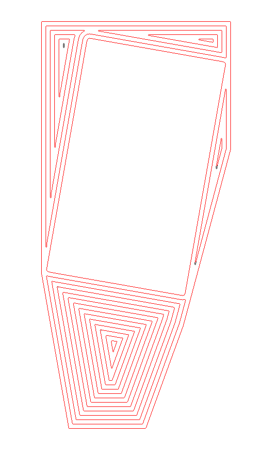
Red overlays indicates well formed print roads.  The black residue shows where the routine failed.


You can see the failures circled in blue.  Looking a bit closer at a few of the failures you can see that the routine breaks down when the distance between two parts of a print road drops below 0.2 mm.  That's a ridiculous case, but slice and dice routines regularly encounter ridiculous cases.  Here is a typical one.


Here you can see that the pathfinder routine jumped the 0.1 mm gap between two sections of the path.  Another thing that became obvious is that the routine can't handle paths which are less than 1 mm in their greatest dimension.


None of these faults are serious enough to cause me to continue working on the code at the moment.  I'm back to printing.

Saturday, August 14, 2010

Peeling parts off of the raft


I am rather far along in the finger design for the telepresence hand. Now that I have flexible sensors and a need to modify the design to accommodate them, I decided to take the time to reduce the width of the finger design to something approximating my own finger. This entailed reducing its width by 25%.

Doing that was a simple matter of rescaling the STLs in Art of Illusion for the narrower width. Once done, however, the phalanges were so small that using the belt sander to take off the raft was something that was no longer practical.

Heretofore, I have simply printed the raft and part all at 240 C and used the belt sander to take off the raft after printing. With the more delicate narrow finger phalanges, however, I could not hold the parts in my fingers safely and had to use pliers to hold them for the sanding. Unfortunately, getting even removal of the raft by that method was a sometime thing.

After a few goes with the delicate phalanges, I decided that it was time to upgrade the Slice and Dice code to vary temperature by layers in order to make the part separable from the raft.

I use a rather traditional raft with heavy, widely spaced print roads for the first layer to even out any misalignment of the print table and flaws in the print table. I print this at a print speed of F240 and an extrusion rate of S360. For the next and last layer of the raft I quadruple the print speed to F960 whilst keeping the extrusion rate the same. All of this is done at a print temperature of 240 C.

What I decided to do for a removable raft was to keep the first layer as it was and then add a third layer to the raft. The second and third raft layers were to be printed at a lower temperature and then the print itself done at 240 C as before.

I did a series of prints lowering the temperature of raft layers 2 and 3. The sweet spot seems to be at about 215 C. At temperatures higher than that adhesion between raft layer 1 with 2 is too high and adhesion between layers 2 and 3 and the print object is too high as well. I could not get reliable extrusion of ABS at temperatures lower than 215.

The new print protocol produced a raft and print which were reasonably easy to separate with one's fingers as you can see here.


the bits of layers 2 and 3 sticking to the printed part are easily removable with either the belt sander or a piece of conventional sandpaper in just a few moments.

Sunday, August 08, 2010

Finishing the reel


I discovered that while the mismatch of inner and outer loops can be sorted out on a single slice fairly easily, things get tougher when you have successive slices getting smaller as I do with the 45 degree angled slopes on the servo reel.

What I did was to make two halves of the reel with boolean operations like this...


Slice and Dice lets me control the print roads on each slice, so I simply arranged it so that inner and outer loops did not meet on one side...


...and left off loops on the other side to make the reel into two halves that fitted together.


So, it was effectively back to glued together plastic model airplane dodges again.


Saturday, August 07, 2010

Improving print roads calculations


In which your narrator rewrites the Slice and Dice routine that calculates print roads on a slice.


Having got a working finger design for my telepresence hand project, last weekend I set about to rig it to a servo motor to see what issues would come up. One of the items needed was a reel which screws onto the servo which takes up the tendons on the finger and moves them in concert.

The 40 mm reel looks like this...


I wanted to make the reel solid since it will be under considerable torque.  To achieve that I used my concentric print roads option rather than cross hatching.  I am not fond of cross-hatching mostly because the join between the perimeter of a print and the cross-hatching is so often mechanically poor.  Using concentric print roads yields a much stronger print.

I calculated concentric roads very simply by painting a strip of pixels on the boundary of the slice to create an interior print road, deleting the strip to define the print road and then painting another strip inside of the new, smaller boundary.  I repeated that simple process until I ran out of slice.

Heretofore, I'd used concentric prints for relatively shallow prints like this phalange...


This looks pretty good.  I had been quite happy with the concentric roads routine till I applied it to the spool.  The spool was a deep object, 40 mm in diameter with an interior and exterior boundary.  You can see what happened...

The roads track the original boundary quite nicely till you get 6-8 roads away from the boundary.  Then, geometric features of the original boundary are sufficiently magnified that the roads bear little resemblance to the shape of original boundary.  The reel provides a really nasty example of this kind of distortion.

The reel that resulted was actually very strong, but looked nasty.  Last night, I undertook to see if there was another way to do the job.

After several false starts, I discovered that if I began with the original slice boundary in one picture box and then mapped a filled circle of the proper radius onto each pixel in the boundary I got extremely smooth print roads.  The reel slice you were first shown looked like this with the new routine...


You will notice that the interior and exterior boundary roads match each other very well but show a gap between the interior and exterior roads.  The hole in this slice of the reel is a screwdriver access port for securing the reel to the servo drive shaft.  The dimension in this slice is just big enough to pass the screwdriver tip.  I widened that access port by two millimeters and the problem with the roads mismatch disappears as you can see here...

The reel consists of two parts; the reel itself and an insert which is glued into a recess in the reel which seats over the servo drive shaft and allows for a screw to secure it.  You can see how this works in this exploded view of the ensemble...


As designed the print road pattern for the reel slice defining the recess for the insert looks like this.

If you look closely you will notice that the meet between inner and outer roads is a bit tight.  The outer dimension of the insert is not critical and can be adjusted a bit to even that out.  Care must be taken, however, to not compromise the roads in the insert in the adjustment.

The more experience I get printing dimension critical parts the more I understand what a balancing act getting the proportions is.  When you are printing a critical part you can't just slap it together in CAD, pump out an STL and print it.  The print road cross section is an integral part of your design and you have to exercise considerable cunning in making everything work together.  This experience is much like what I learned after I graduated from architectural design studios eons ago.  It's easy to design something that looks nice if you have any sense of aesthetics at all.  Designing something that looks {or works} nice that can actually be built is a far harder task.

In any case, I've got the new print road mapping routine running rather well and am going back to work on my telepresence hand project.

Wednesday, August 04, 2010

Applying VTEC to Slice and Dice


In which your narrator lowers the execution time of Slice and Dice by upwards 90%.


Now that I am well into designing the hand for my telepresence project, I am running into the limits on the processing speed of Slice and Dice in the design cycle. In the past, I could run the code through a good wash and brush up and reduce the execution time by 90%. That would take about a man-week that I don't want to spend. Instead, I chose to take advantage of a characteristic of the parts I design to achieve faster execution speeds.


Typically, I have been designing parts that look somewhat like this.


When you look at it closely, you notice that there are really only two different cross sections through the vertical axis.


Now Slice and Dice as I wrote it is not particularly bright code.  I wrote it to be simple, not efficient.  When you slice this object into 0.25 mm wafers you get 39 slices that look something like this.


Slice and Dice tediously processes each slice as if it were unique.  I took a day off to see if I could take advantage of the geometric repetitiveness of my parts.  To do that I initially thought to simply match each image with succeeding image and throw out the duplicates.


Life wasn't quite that simple.  While the slices looked identical, miniscule differences in the way the slicing routine interacted with triangles showed up in the flooded pictures seen above.  I did find, however, that if I allowed flaws in the pixels of up to 0.2%  of the total in the flooded images the 39 images were reduced to exactly 2...


Which is what you would have expected if the slicing had been geometrically perfect.  Thus I had to do cpu intensive processing on two slices instead of 39.  That saved about 94% of the processing time that I had previously been using and got my processing speed into the range I was used to seeing with Skeinforge.


As an added advantage, the reduction routine picks up broken slices very nicely.


This approach would not, I think, work with a programme like Skeinforge or, unless I misunderstand how it works, Netfabb.  It could, however, easily be applied to Adrian's host code for Reprap.

Sunday, August 01, 2010

Printing in trays


Ordinarily, I like to print parts one at a time while I am design them. The telepresence finger, however, has reached a rather advanced state, so I've written a small script to shuffle two print files together so that they can be simultaneously printed.


The travel time between prints gives them a chance to cool and lets me print much smaller isolated features like the post circled in red successfully than would otherwise be possible.

Wednesday, July 28, 2010

Some thoughts and observations about having a Reprap machine in the design cycle


In which your narrator reflects on the rather radical difference between what he perceived the design process would be pre and post the advent of practical Reprap printers.

Do you want to read more?

From 2005 till November of last year, I spent most of my free time trying to build a Reprap printer. It was good fun and I learned a lot of things. Mostly, I learned how not to be intimidated by technology that I was not familiar with. For me, this was an extremely valuable lesson.

When my day job began to require more and more of my attention towards the middle of last year, my development of Tommelise 2.0, my own repstrap project began to suffer. Finally, at the end of October I sat down and did an unpleasant assessment of my situation. I could continue to work on Tommelise, or I could simply buy one of the Reprap-derived kits that were beginning to emerge from small enterprises started up by other core team members. I estimated that it would take something like another 6-8 months to get Tommelise 2.0 printing properly. I subsequently ordered one of Ian Adkins' Rapman 3 printers.

Rapman 3 is a re-engineered clone of the first generation Darwin design. I bought it rather than the somewhat cheaper Makerbot primarily because it had a substantial print volume but also because an associate, Batist Leman, had been blogging his experience with the model. Batist was very impressed with the Rapman and communicated that very well through his video clips of it in operation.

Prior to November, I was designing and making parts with the object of making a Reprap machine. Afterwards, I was designing and making parts WITH a Reprap machine. The distinction can be easily lost on those who have not used a Reprap machine.

What I have discovered in the eight months since is that the availability of a Reprap machine makes a massive change in one's design practices.

Prior to November I lusted after a professional 3D CAD package. Features like dimensioning and reliable boolean operations cluttered my thinking. The problem was that I was thinking like an engineer, viz, I wanted to make careful designs in 3D and then have print them out on an accurate 3D printer. I no longer feel that way.

With the advent of Art of Illusion (AoI) 2.8.1, I stopped lusting after "professional" CAD packages even though by that time I already owned several. My design cycle now looks like this.


  • (re)design (a) part(s)
  • print the part(s)
  • manually and visually see how the parts work together
  • repeat the process until satisfied
Precise dimensions became not very important while things fitting together properly did.  The linkage between these two factors was not as strong as one might first suppose.

With a Reprap printer it became a simple matter to run through a dozen design cycles to get a parts ensemble to work in a matter that suited me. I currently design with the Reprap printer as part of the design cycle rather than using it as a final step after design cycles are finished.

At the beginning of this year Skeinforge, which I had been using previously, went through a rough spot.  This encouraged me to invest in the upcoming Netfabb software prior to its release.  As the Skeinforge rough patch continued and the folks at Netfabb's release dates began to slip, I finally became frustrated and then angry.  I wasn't able to do the design work I wanted.

In frustration, I unearthed my old Slice and Dice code from the Tommelise project and began to bring it up to date.  Having used both Skeinforge and the nascent Netfabb offering to process STL files into print instructions I evolved a very different approach to processing solids files than what either of these two products offered. 

Both Skeinforge and Netfabb basically take your STL and give you print instructions.  They do it very quickly and efficiently.  Unfortunately, if you have a dodgy design file they can produce some very crazy print files.  Ones ability to respond to crazy print files is, perforce, limited.  With both Skeinforge and Netfabb, the majority of craziness is generated when ones STL files are flawed.  The need for perfect STL files had fueled my previous lusting after "professional" 3D CAD packages.

I responded with Slice and Dice by internalising Mandelbrot's maxim that noise is always going to be there and it will be unpredictable.  Instead of striving for perfection, Slice and Dice concentrated on giving me options to deal with imperfect design files.  I began by keeping each slice of a design file as an image that I could bring into simple image handling tools like Windows Paint and manipulate.  Paint let me patch and alter flawed slices to suit myself.  I no longer needed a "professional" 3D CAD system.  AoI was just fine for my purposes.

From there, I discovered that if you use 2-3 print roads to define a print's perimeter you wind up with a strong part even without infill.  I began working to improve my control of perimeter print roads and soon found that I could make parts not unlike those in old fashioned plastic model airplane kits which used injection-moulded parts that you glued together.  Infill became unnecessary in all but the most extreme cases.  Hollow parts were tremendously quicker to print and not nearly so prone to warping. as "solid" parts.  I don't use a heated bed and doubt that I will anytime soon.

Conventional Reprap thinking views a 3D printer as being able to print, more or less, any 3D object.  Development has concentrated on infill and support materials to achieve these ends.  Both are wasteful of printer time and materials, in my opinion.  I try to design parts which keep in mind the strength and weaknesses of my printer.


As you can see with this telepresence 'bot finger, I think I am getting pretty good results.

Monday, July 26, 2010

Memories of plastic model airplanes


In which your narrator harks back to his youth and fingerprints ruined by trimming plastic flash off of model airplane parts with double edged razor blades.

I have an aversion to infills. Recently, I realised where the aversion came from. During the 1950s you could buy plastic model airplane kits for $1-2. These were made with injection moulded parts that came on little flat plastic Christmas trees. Exacto knives in that era were both expensive, for a child at least, and the blades dulled quickly and were largely beyond the ability of a child to resharpen. As a result, this child nicked paper-thin double edged razors from the medicine cabinet to trim the parts off of the tree and trim the flash off of the parts.

That worked fine, except for the cuts which the blades would make on ones fingertips which eventually grew into permanent scars. That was no big deal in those days.

Having trimmed your parts you glued them together with Testors or Duco cement {ethyl or butyl acetate} and, with a bit of paint, you had a lovely airplane to hang off of your ceiling by a thread and dream about flying.

Early on in the Reprap project, we used Solarbotics gearmotors. When you opened one of the gear boxes of, say, a GM-3 you found that the housing had been made using the same injection moulding process that model airplace manufacturers used. With a working Reprap printer I quickly began to loathe the clumsy, infilled parts that we were designing. They wasted both time {to print} and filament as well. Worse still, one tended to stick the parts together with expensive nuts and bolts.

Why not make parts that fit together like the old model airplanes?

The trick there is that the old model airplanes inevitably had a left side and a right side or a top a bottom that were often simply mirror images of each other. This weekend I was design a finger tip with left and right sides. I had designed the left side and got it working acceptably and was going back to do the right side in Art of Illusion {AoI} when it occurred to me that it would be much simpler to just write a script to swap the sign of the coordinates of the axis that I wanted to mirror around. Writing that script took about five minutes and saved me a lot of time in redesign and reprocessing of the resultant STL since my script operated directly on the Gcode.

Printing the two halves was trivial.


It took a few moments to scrape off the raft and a few drops of cement to finish the part.


The result was an elegant looking part that would have been a right bastard to design and print conventionally.

While I've incorporated this simple mirroring script into my own Slice and Dice STL processing software it would be no big deal to incorporate it into the more widely used STL processing routines available to Reprappers either open source or commercial.

Sunday, July 18, 2010

First prints


Slice and Dice is pretty much working now. I'm not completely happy with how the infill and the perimeter prints hook up, but that's mostly parameter tuning. I'm debugging Slice and Dice while I am designing a robotic hand. Here is the distal phalange {finger tip} that I've done for a first try.


I've left out the infills in that they are not necessary.  Here you can see the first print that I am happy with.


I've really got to break down and find a camera that can do better closeups for small objects.  My periodontist uses one for photographing teeth, an Olympus, which might be the ticket.  I may well buy one after my quarterly tax payment is done towards the end of this month.


As you can see in this second pic, there is a separation between the outer and inner print road for the flexural axis.  I've got to reduce some the outer radius there or lower the extruder flowrate and go for three print roads instead of two on that part of the print.

Saturday, July 17, 2010

In production


Got the whole Slice and Dice ensemble running together last night and did some test prints. Vectorization cured up the extruder head slowdown completely for curved print roads. Sweet! :-D

Saturday, July 10, 2010

Operational again


I was able to put the final touches on the Slice and Dice upgrade last night. The app is operational again. Now I can get to work on that telepresence hand project. :-)

Tuesday, July 06, 2010

Vectorization of pixel defined print roads actually working properly


In which a very kind Adrian Bowyer takes pity on your narrator.


In my last posting on 21 June, I laid out a method for vectorizing a pixel-defined perimeter. Having read the posting, Adrian Bowyer, a published expert on this sort of thing, took me aside and showed me how to do the vectorization efficiently instead of just at all, the solution I came up with.


Using Adrian's approach, I was able to achieve my goal of getting exact vectorization of the print road and push out the average segment length to well over the 0.3+ mm that was required to assure a print head speed over the major axis of at least 16 mm/sec.


You can see an example of such a vectorization here.  All values, save the last, are in tenths of a millimeter.


The last value in the listbox, "rho/axis" should allow me to adjust the print speed on the fly in G1 statements to assure a constant head velocity for print road segments greater than 0.3 mm in length.


I should be printing ABS parts again by this weekend, which is good since I want to redesign and print one of these.


Monday, June 21, 2010

Vectorization of pixel defined print roads


In which your narrator describes the end, hopefully, of a search for a reasonable way of converting pixel-defined print roads calculated by Slice and Dice.

For the past two months I've struggled with what has been, for me, a very nasty problem, viz, converting pixel boundaries defining print roads for my Rapman printer into equivalent vector descriptions.  As I mentioned previously, in order to get a major axis velocity of 16 mm/sec on the SD card Rapman 3.x you have to have GCode vectors of no less than 0.3 mm.  If you are printing detail finer than that the lag caused by reading off the card and processing the GCode slows down the print head dramatically.

From my literature search, vectorization is a fraught process, especially if you are not willing to accept considerable degradation of your pixel-defined road.  With 3D printing, perforce, we really can't accept degradation.

Over the last few weeks, I've finally confected a method which seems to do the job.  As with most things I do, it is relatively simple and straightforward.

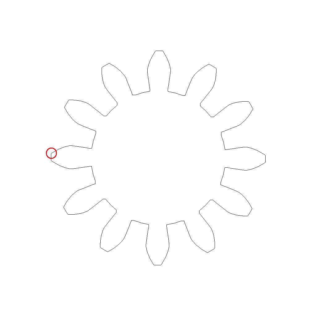
Suppose we have a perimeter path for an involute profile gear...

The method grabs a 2.1 mm patch {note the red circle} at the extreme left of the path which you can see here...


Here you can see the individual pixels making up the print road.  The first thing we do is define the starting point and direction of the road from the centre of the patch.


At that point I pivot a scan from the center of the patch and identify the closest fits at ranges varying from 1 pixel to 11 pixels.


In this case, the longest perfect fit to the involute profile was 4 pixels.


Red pixels represent the fitted vector while blue indicate the remaining pixels.  Notice that this vector is four pixels long, just enough for the Rapman to operate at 16 mm/sec.

The patch is then re-centred over the most distant red pixel and the process repeated until the full loop is vectorized.

Looking at a simpler problem, consider a hexagonal print road...


Isolating the beginning of the print road yields...


Scanning this straight line gets a perfect match at 11 pixels.  Thus the way I have the code set up now creates vectors of up to 11 pixels in length, a maximum length of about 1.4 mm.  It's reasonable to ask why the vectors are kept so short.  In fact, it takes much longer to process the print roads with longer vectors and there is no reason, SD cards having huge storage capacity, not to have large print files.

As I get time in the coming weeks I will be fully embedding this method into Slice and Dice.

Sunday, June 13, 2010

New blog...


I've finally done enough work on my active telepresence project that I need a blog to document what I am doing. For anybody interested, you can access it here.