
Saturday, December 17, 2011
Friday, December 16, 2011
Solving a nagging question about print adhesion
Unlike most of you, I don't use an electrically heated print surface. Some time ago I bought a Rapman 3.1, which used an acrylic 3 mm print table. I soon discovered that 3 mm was far too thin and quickly warped beyond use. Switching to 10 mm solved that problem.
After a long time of successful prints, I noticed that with winter causing colder temperatures in the print room I was having more and more trouble getting my prints to stick to the acrylic. I tried cleaning it and sanding it with little avail. Electrically heated print tables were just coming available but insofar as printing was concerned, I thought that things were already complicated enough without adding that sort of equipment to my Rapman.
I had an IR heat lamp in the lab, detritus of another experiment, and discovered that using it on a tripod to raise the temperature of the acrylic print table above 40 degrees Celsius measured with a non-contact IR thermometer gave me consistent adhesion. I soon discovered that I could turn off the IR lamp after 4-5 print layers with no ill effects. It was not needed for the rest of the print.
The rig looked a bit like this...

Note that the lamp is placed at a 45 degree angle to the acrylic print table.
I soon noticed that adhesion at the near side of the print table was much less firm than that at the back and less firm at the left side than the right. I attributed this to various things, uneven heating being one of the possibilities. While the left/right difference made sense the front/back difference didn't seeing as the IR lamp was aligned with the left/right axis.
Cranking the terminal heating temperature before starting a print to about 50 degrees solved most of the problem for the center of the table and I was able to print along the front/back axis with reliable success. Unfortunately, the back side of the print area seemed to have the print pad melting into the acrylic while the front side would separate easily.
It made no sense. I thought for a while that it had something to do with the acrylic plate and rotated it with no effect. Swapping ends and sides always left the back side of the print table very firmly attached to the print pad. While that wasn't a horrible situation it was annoying, because it meant that processing the printed objects after separation became more time consuming.

A few weeks ago, I purchased a FLIR E30 thermal imaging camera with the intention of learning more about what was happening with prints as they were being laid down, the ultimate goal being building in advanced heuristics into my Slice and Dice app which converts STL files into Gcode. I also had hopes about eventually doing some research into what actually happens thermally with extruder hot ends with the notion that I might be able to design a better one.
Yesterday, the E30 arrived and I decided that a good beginning exercise might be to look at the distribution of heat on my acrylic print table when I used the IR lamp in its standard configuration to heat it. The results were quite unexpected.

>
The lamp put down a marked hot spot at the upper right rather than at the right as I expected. The upper right was exactly where I had the most trouble with print pad melting. Obviously, the IR lamp did not give even heating when tilted but overheated in on the upper right.
This was nasty. I had previously thought about using several smaller IR lamps at the corners of the Sampo printer that I have been developing. If the smaller lamps behaved like my single, large one, however, this might not be a good idea at all.
I then got to thinking about how IR lamps are actually used in food heating cabinets. They are almost always placed point straight down. I rearranged my tripod to place the lamp almost vertically over the acrylic print table.

That sorted out the temperature distribution problem...

Friday, December 09, 2011

Tuesday, August 16, 2011
Sampo's touch screen begins to work...
Adriaan has been working hard learning the TFT programming protocols and has his first touch screen menu working on the Sampo controller board.

Wednesday, July 27, 2011
Bogdan makes a measurement suggestion...
After I got the x and y axes operating independently, Bogdan suggested that I measure the steps between the limits switches to see how much difference in measurements might be attributable to the mechanical microswitches that I am using. I had already been recording that with the y axis, so I decided to extend the monitoring code a bit.
With the y-axis, I had been simply writing the number of pulses to an SD card whenever a limit switch was tripped. In that I was running the axes at 65 mm/sec, I was getting a rather substantial thump whenever a switch was encountered. When I thought about it, I began to suspect that the impact was a result of the time it was taking the write to the SD card to happen in that I was doing that immediately after the switch was tripped. I changed the code to record a set number of triggering events for each axis and then exit the stepper loop and print the whole set of measurements at one time. That reduced the noise of switch triggering on the x axis to almost nothing. It also reduced the noise from triggering events on the y axis, but not as much. Considering the y-axis is shifting the whole weight of the x axis assembly, the extra momentum generated thereby is probably causing the larger thump.
I first took a set of 50 triggering events running at 65 mm/sec.

You can see that the two limits switches on serving the x axis trigger with slightly different sensitivities, one triggering about 0.3 mm greater than the other {transition is running at 0.89 mm/step for both axes}. The both y axis limits switches trigger at the same place except that occasionally one gets moody and triggers 8 steps {~0.6-0.7 mm} longer than the first.
I then took another set of measurements at 32.5 mm/sec. The NEMA 23s were near resonance frequencies at this speed raising the noise level of the printer considerably. I will have to see about damping this.

What you can see is that the variation on the x-axis stayed about the same while the moodiness of the one limit switch on the y axis disappeared. Notice also that the steps between switches are down.
From there, I took a set of measurements at my usual printing speed for Rapman at 22 mm/sec.

Decreasing the transition velocity got us further away from the resonance frequencies of the NEMA 23s. It must be said, however, that the printer was still louder than when I was running it at 65 mm/sec. You can notice here that the variation in limit switch triggering has dropped to 1-2 steps.
This has been an interesting exercise. One thing that is obvious now is that to control noise levels I should be controlling the stepper speed both by the delays between steps and by adjusting the level of microstepping that I am using.
X & Y Axes operational from the controller
I was finally able to get time to integrate the full anti-bounce board with the x and y axis limit switches.
The two axes are playing ping pong and running at a speed of 65 mm/sec with no slippage and no heating of either the steppers or the driver chips. I've run them all morning with no mishaps.
Now I am going to have to see to writing a gcode interpreter and taking a shot at the TFT 320x240 graphics touch screen for system control.
Wednesday, July 20, 2011
Leveraging Bogdan's anti-bounce circuit for Sampo...
In developing the Darwin-derivative, Rapman-derivative Sampo 3D printer project as a kaizen exercise I utilized the same sort of microswitches for limits checking as are specified in the Rapman design. I soon discovered that the switches have a formidable electronic bounce. I was able to control that using the button function in my firmware compiler for the y-axis. The computations taken for a firmware fix, however, were going to put a terrific drag of my MCU that I didn't want to have to deal with.
Enter Bogdan Kecman with helpful suggestions on how to put together an antibounce circuit for the limits switches.

I had last built an antibounce circuit in 1981, so his help was greatly appreciated. I built a lashup of the circuit to check to see that the component values were right and then went on to design a board to handle all six limts switches. I wanted six instead of Rapman's three because a lot of problems that I'd had with Rapman stemmed from the fact that it has limits switches only on one end of its axes. When things went bad one could find steppers trying to skate off of the unchecked far end of axes. As well, Rapman limits checking only seems to be done when one is resetting the axes at the beginning of a print. I want to do better than that.
I bought components and dug out my stripboard and had a go at the design. Some time before I put together a stripboard design program after having had no luck with the ones I was able to access on the web. Eventually, I evolved this board.
Frontside...

Backside...

It has been some time since I built a board, so I found putting this one together quite frustrating. I was about to give up this evening after making a bunch of mistakes and then got angry to the point of rage. The adrenalin let me get the @#$#@$ thing finished.

Tomorrow I will drill out the breaks in the strips, check the board for continuity and, if I have enough time, try to rig it into Sampo and extend the firmware to utilize it. I suspect that will have to wait till the weekend, however.
Wednesday, July 13, 2011
Mendel z-axis stepper mounts done
I managed to get some hours together to do some more work on my son's Prusa Mendel, the z-axis stepper mounts this time.

I printed the z-axis stepper mounts at a 45 degree angle to minimize parts preparation time and avoid warping.

I'm now working on the x-axis stepper and idler mounts. My son processed the stepper mount last night and I did the idler mount this morning. They're printing this evening.
Sunday, July 10, 2011
Mendel frame takes shape...
I had a major crash of the Rapman 3.0 printer and for several hours I thought I was really knackered. One of the leads to a phase of the extruder stepper parted because of fatigue from thousands of hours of vibration. The system shut down and reset. At first I thought I had a simple static discharge event, the first in many months. I fired the system back up and discovered that the extruder stepper would dance around but wouldn't pump filament.
After serious prayers that the stepper driver chip for the extruder hadn't fried I rewired the connector and got the extruder pumping ABS again only to discover that the intense vibration from the stepper before the reset had actually shaken apart the Arcol extruder hot end that I had bought from László Krekács in Hungary.
This sounds worse than it was. I simply screwed it all back together and cleaned the extruder end and it worked perfectly again. Unfortunately, I will have to recalibrate Rapman now. That should take a few hours that I didn't have available today.
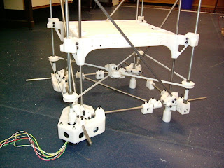
In any case, I was able to cobble the Prusa Mendel frame together this morning.

It's a dinky little thing, but interesting all the same.
Saturday, July 09, 2011
Printing a Mendel derivative
After talking with my son recently, I concluded that he needs to start printing a lot faster than I'm going to have Sampo debugged and duplicated. I have a lot of 8 mm linear shafting and linear bearings in stock, so I decided to build him a Mendel derivative using Sampo firmware and controllers. That should get him printing a lot faster than would otherwise be the case.
I started printing parts for a Prusa Mendel yesterday. So far, so good. Got the gantries finished and am printing the rest of the parts now.

5/16th inch threaded rod is pretty much a one on one replacement for M8, #8 machine screws replace M4s and #4 machine screws replace M3s. I couldn't see much point in printing the SAE Mendel. I'm going to have to redesign the extruder carriage to seat linear bearings instead of those strange PLA things it ordinarily uses.
Tuesday, July 05, 2011
Picking up speed
The MIPS core that PIC32 uses is a very high performance CPU that was used in high end Windows workstations in the early to mid-1990s. It doesn't behave much like the 8 and 16 bit PIC chips, so it's taken me a while to get down the learning curve. The button function in the Mikroelektronika compiler library works, but requires about 10 msec to filter out the bounce when a limits switch is encountered.
Processing a button function for each step when I was running at half step slowed the y-axis down to 12-15 mm/sec. To get around that problem in firmware I wrote a smart limits switch routine that runs slow until it finds the first limits switch and then kicks the stepper motor up to full speed until it nears the other limits switch.
Using this approach lets me increase the maximum transition speed for the y-axis from 15 mm/sec to about 65 mm/sec for my firmware testing as you can see in the video clip.
It's worth noting that the Allegro driver chip has a maximum rating of 0.75 amps and the NEMA 23 is a six wire model drawing 0.5 amps per phase. I've wired it in series which brings that amperage down considerably. In spite of this I'm getting 65 mm/sec and both the stepper and the NEMA 23 are running quite cool. The driver chip requires no heat sink or fan.
Monday, July 04, 2011
Y-axis test firmware operational
After a delightful chat with Bogdan this morning about the PIC32's MIPS core processor, I was able to get the y-axis test firmware working. Bogdan has done a lot of work with the PIC32 and is very generous with his knowledge. A few hours later, I had the y-axis responding to the limits switches.
Right now with sampling from the limits switches in the same loop that runs the stepper I'm getting 15 mm/sec. On its own the stepper can do about 52 mm/sec. I suspect that the speed of the axis will be getting a lot closer to that upper limit once I get the limits switches into an interrupt loop. :-)
Right now with sampling from the limits switches in the same loop that runs the stepper I'm getting 15 mm/sec. On its own the stepper can do about 52 mm/sec. I suspect that the speed of the axis will be getting a lot closer to that upper limit once I get the limits switches into an interrupt loop. :-)
Wednesday, June 29, 2011
Printing flexible cable guides...
There is not much to say about this. Once I got two of the links printed and assembled so that I knew everything fit together, I bought a few hundred #4-40 3/4 inch machine screws and nuts to hold the parts together. I'd designed the parts to perfectly seat a 3/4 inch machine screw and nut.
When I got home with my trove of fasteners from my stockist I discovered that his Chinese supplier had been making a little extra money by trimming his 3/4 inch screws (0.75 inch) down to 0.714. What that meant was that the screws went all the way through the guide assembly but didn't emerge on the other side to allow the nut to be seated on the end of the machine screw.
My stockist is getting me some 7/8 inch machine screws as replacements and writing a hot note to the warehouse. Quality assurance at the Chinese plant needs a bit of a rework, I think.
Interestingly, I had designed the holes for the #4 machine screws so that the threads engaged the sides of the holes, so actually nuts weren't required. With that in mind I went ahead and assembled the flexible cable guide for the x-axis. It seems to work perfectly.

I get a tight turn like I'd hoped with no clashing. Right now I am up to 16 inches of a 24 inch assembly for the x-axis. When I get the full 24 inches printed and assembled I will design and print the end mounts.
It will be interestingly how many hours of operation this kind of flexible cable guide will handle before something wears out.
Sunday, June 26, 2011
Flex cable carrier
I've never been happy with the way that Rapman handles axis and extruder cabling, so I decided to print my own flex cable carrier system. I saw several possibilities in Thingiverse. Most of them were knockoffs of existing injection molded parts, however, and printed very poorly.
A few looked as if they were designed specifically for a 3D printer like this one...

I didn't much like this one largely because of the large turning radius for the flex. I wanted something more like this...

The system can make a 180 degree flex within 50 mm. The next move is to get a couple of packets of #4 bolts and nuts and print a few feet of this to try with the x-axis cabling.
A few looked as if they were designed specifically for a 3D printer like this one...

I didn't much like this one largely because of the large turning radius for the flex. I wanted something more like this...
Since my wiring was considerably more modest, however, I wanted something with a bit sharper turning radius still. After several hours of trying out alternatives in Art of Illusion, I came up with this as a first try.

It is shown here with #4 bolts 1.5 inches long. It can work interchangeably with #4 UTS/SAE - 3/4 inch or M3 - 20 mm bolts. With fasteners it costs about $1.50/ft. Commercially available alternatives average about $12.50/ft.

Tuesday, June 14, 2011
A "string wars" approach to the y-axis
Darwin and it's direct derivatives uses two belt loops driven by a shaft connected to a NEMA 23 stepper.


In Sampo, that dual loop arrangement has been replaced with a single large loop

The belt guides are equipped with standard 608 skateboard bearings with printed fenders.

Topologically, the y-axis is simply an attenuated version of the x-axis.

Tuesday, May 31, 2011
Print table installed
I had gone to considerable trouble to make sure that I sited the bolt holes in the MDF {medium density fibreboard} print table properly. To that end I designed a template for each of the brackets that would show me where the guide holes should be put.

Once I had the table suitably aligned, I was able to drill the guide holes with my Dremel tool quite easily.

I then removed the table and took it to the workshop to drill out the holes to #8 bolt diameter. When I returned and tried to mount the board I discovered that the holes didn't line up. I had neglected to mark the lower left corner of the print table and had no way of knowing which side our orientation matched my drilled holes. We are talking about a few mm here, mind. There were 16 possible orientations and that was complicated by the fact that the brackets were able to rotate around the z-axis linear shafts in the xy plane. After about the tenth possible orientation, I found one that fit 3 of the four brackets and just redrilled both the MDF and the bracket. Mercifully, solid ABS is very amenable to drilling so other than having the lower right corner showing an extra set of bolt holes, it all worked out quite well.
Hopefully, I will remember to mark the lower left corner the next time I build one of these. The print table moves quite freely as the video will demonstrate.
Now all that remains is for me to reprint the z-axis cable grippers and mount them and the z-axis will be complete.
Monday, May 30, 2011
Ready to install the print table
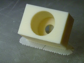
I got the last of the y-axis brackets printed and light mounted.

It looks like the print table with be 420x420 mm. I've designed a bolt-on template that seats the table on the brackets and shows me where to site the guide holes for the mounting bolts.

And here is the first drill template mounted on a z-axis bracket.

Got it right on the second try! :-)
It looks like the print table with be 420x420 mm. I've designed a bolt-on template that seats the table on the brackets and shows me where to site the guide holes for the mounting bolts.

And here is the first drill template mounted on a z-axis bracket.

Sunday, May 29, 2011
Stepping into firmware
Having had good experience with the Rapman's PIC32-based controller, I decided to stick with that MCU for my new printer. As I mentioned earlier, rather than buy a $1k+ C compiler from Microchip, I bought a much less expensive, full-featured BASIC compiler for the PIC32 {they also offer C and Pascal compilers} and a full development board from Mikroelektronika in Belgrade. Friday night, with the last of the z-axis brackets being printed on my Rapman and the 19 June exhibition in San Francisco coming up, I decided that I'd better get cracking on the firmware.
When I bought the PIC32 development board from Mikroelektronika, I also picked up a little stepper controller board from them.

It uses an Allegro A3967 driver chip rated at .75 Amps. Now ordinarily I wouldn't have considered getting such a thing, but in this case it seemed reasonable to have a ready made stepper tester board that I knew worked with my development board and I knew I had a number of small stepper motors that I could use with it. Nothing I'd consider using on the printer, mind, but all the same useful in the learning process.
Like Darwin and Rapman, I'd decided to be conservative and use NEMA 23 steppers. The price on these has dropped dramatically since we were building Darwins several years ago. While shopping for NEMA 23 steppers, I happened across this little jewel.

Oddly enough, this 6 wire NEMA only drew 0.4 amps but produced a lot of torque. I bought it, too, just so I could have have a NEMA the right size that I didn't necessarily want to use on the printer. At that time I was looking at using the much heavier capacity Pololu stepper drivers that have recently proved so popular with Mendel electronics.
Now here is where serendipitous good fortune intruded. The firm selling this stepper also had a special on 24 volt power supplies.

When we began with Reprap about the only reasonably priced power supply we could lay hands on was a salvaged 5-12v ATX box out of old PCs. 24 volt supplies at the time were quite dear. We knew very well that we could get a lot better performance out of steppers if we used 24 volts, but nobody wanted to invest in a 24 volt supply. This bad boy put out 6.5 amps at 24 volts for $19. The economics of that were hard to argue with given that my development board power conditioning circuit would eat anything up to 30 v DC.
Friday night and Saturday I spent the necessary hours skating down the learning curve of the Mikroelektronika development board and compiler IDE. This took longer than it should have in that the PIC32 boards and compiler are very new to Mikroelektronika. As a result, while they had code samples in BASIC for their stepper controller board, they were for 8 bit PIC chips and development boards, not their new 32 bit offerings. I don't know why firms don't offer extremely simple sample code patches. Instead, they always clutter it up with nonsense that runs LCD boards and makes LEDs flash on and off prettily. Of course, how that works on an 8 bit board is very different than it is for a 32 bit board.
By Saturday afternoon, I'd managed to unclutter and migrate their code to PIC32 and had the stepper controller connected to the NEMA 23 working properly.

I knew there was a lot of friction in my cable z-axis system, so I did an initial gear design of 3.5:1 to insure that I got plenty of torque. I had rigged the 6 wire stepper in series at Bogdan's suggestion so that the amperage pull was considerably below 0.4 amps. Imagine my surprise when I discovered that there was ample torque even at half-step to happily push that stiff z-axis lead screw collar back and forth under serious load at 660 pps, a step rate just short of the resonance speed of the stepper. Even under those loads the controller chip never got above about 50 C even after several hours under load. That means that no heat sink is necessary.
When you translate that pulse rate out to an MXL belt driven x or y axis powered by an 18 groove pulley you get a calculated top speed of about 60 mm/sec. That's about three times the head velocity that I print at. It would appear that running a stepper with 24 volt power makes a very big performance difference.
Here you can see the stepper controller attached to the NEMA 23 and the PIC32 development board.

I've been thinking about that cool controller chip and that NEMA 23 and wondering about the possibility of driving a Wade extruder design with a NEMA 23. The technology and economics are certainly attractive.
I'm going to buy some more of those controllers and also a relay card so that I can control the hot ends and heat lamps on the printer.

Mikroelektronika certainly has a very big toolbox of accessory boards that let you prototype just about anything without having to build up circuitry from scratch. They're not as cheap as you could build from scratch, but if you count the time and cost of building up purpose made boards while you are developing a printer and not sure of everything you want in it, they're very cost effective.
When I bought the PIC32 development board from Mikroelektronika, I also picked up a little stepper controller board from them.

It uses an Allegro A3967 driver chip rated at .75 Amps. Now ordinarily I wouldn't have considered getting such a thing, but in this case it seemed reasonable to have a ready made stepper tester board that I knew worked with my development board and I knew I had a number of small stepper motors that I could use with it. Nothing I'd consider using on the printer, mind, but all the same useful in the learning process.
Like Darwin and Rapman, I'd decided to be conservative and use NEMA 23 steppers. The price on these has dropped dramatically since we were building Darwins several years ago. While shopping for NEMA 23 steppers, I happened across this little jewel.

Oddly enough, this 6 wire NEMA only drew 0.4 amps but produced a lot of torque. I bought it, too, just so I could have have a NEMA the right size that I didn't necessarily want to use on the printer. At that time I was looking at using the much heavier capacity Pololu stepper drivers that have recently proved so popular with Mendel electronics.
Now here is where serendipitous good fortune intruded. The firm selling this stepper also had a special on 24 volt power supplies.

When we began with Reprap about the only reasonably priced power supply we could lay hands on was a salvaged 5-12v ATX box out of old PCs. 24 volt supplies at the time were quite dear. We knew very well that we could get a lot better performance out of steppers if we used 24 volts, but nobody wanted to invest in a 24 volt supply. This bad boy put out 6.5 amps at 24 volts for $19. The economics of that were hard to argue with given that my development board power conditioning circuit would eat anything up to 30 v DC.
Friday night and Saturday I spent the necessary hours skating down the learning curve of the Mikroelektronika development board and compiler IDE. This took longer than it should have in that the PIC32 boards and compiler are very new to Mikroelektronika. As a result, while they had code samples in BASIC for their stepper controller board, they were for 8 bit PIC chips and development boards, not their new 32 bit offerings. I don't know why firms don't offer extremely simple sample code patches. Instead, they always clutter it up with nonsense that runs LCD boards and makes LEDs flash on and off prettily. Of course, how that works on an 8 bit board is very different than it is for a 32 bit board.
By Saturday afternoon, I'd managed to unclutter and migrate their code to PIC32 and had the stepper controller connected to the NEMA 23 working properly.

I knew there was a lot of friction in my cable z-axis system, so I did an initial gear design of 3.5:1 to insure that I got plenty of torque. I had rigged the 6 wire stepper in series at Bogdan's suggestion so that the amperage pull was considerably below 0.4 amps. Imagine my surprise when I discovered that there was ample torque even at half-step to happily push that stiff z-axis lead screw collar back and forth under serious load at 660 pps, a step rate just short of the resonance speed of the stepper. Even under those loads the controller chip never got above about 50 C even after several hours under load. That means that no heat sink is necessary.
When you translate that pulse rate out to an MXL belt driven x or y axis powered by an 18 groove pulley you get a calculated top speed of about 60 mm/sec. That's about three times the head velocity that I print at. It would appear that running a stepper with 24 volt power makes a very big performance difference.
Here you can see the stepper controller attached to the NEMA 23 and the PIC32 development board.

I'm going to buy some more of those controllers and also a relay card so that I can control the hot ends and heat lamps on the printer.

Mikroelektronika certainly has a very big toolbox of accessory boards that let you prototype just about anything without having to build up circuitry from scratch. They're not as cheap as you could build from scratch, but if you count the time and cost of building up purpose made boards while you are developing a printer and not sure of everything you want in it, they're very cost effective.
Tuesday, May 24, 2011
Winding up the String Wars
I was finally able to finish making the connection between the z-axis lead screw and the cable turnbuckle for the z-axis positioning system. Given that the 3/8-24 threaded rod moves 0.945 mm per full turn and that the 32:12 gear reduction coupled with the 200 step/full turn for the NEMA 23 we get something like 533.33 steps per turn or 0.00177 mm movement per step.
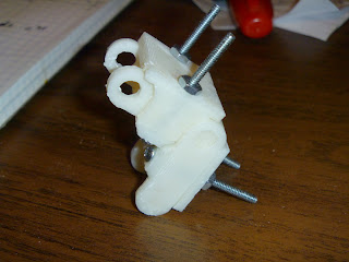
You can see the general layout of the z-axis lead screw with this pic...

I've circled, from left to right, the thrust collar nut, the cable turnbuckle and the linear bearings that make up the elements to transfer power from the stepper motor to the cable.
Here you can see the three connected...

Here is a detail of one of the four cable-driven lifts for the print table with the bracket in place...

I plan on having one fixed joint between the brackets and the table and two sliding joints constrained in the x and y-axes in the two brackets adjacent to it and a sliding joint in the xy plane opposite. I hope that will be stable enough.
Next, though, I have to see if I can finish the design and printing of the BfB hot end adapted Wade extruder derivative. If that takes too long I will fall back on the two full BfB extruders that I have in stock.
Monday, May 23, 2011
NEMA 23 connected to the Z-axis lead screw
With the completion of the gear pair last night, the connection between the NEMA 23 and the Z-axis lead screw is complete.

That milestone meant that I had to move Sampo into the front room so that firmware development could begin.


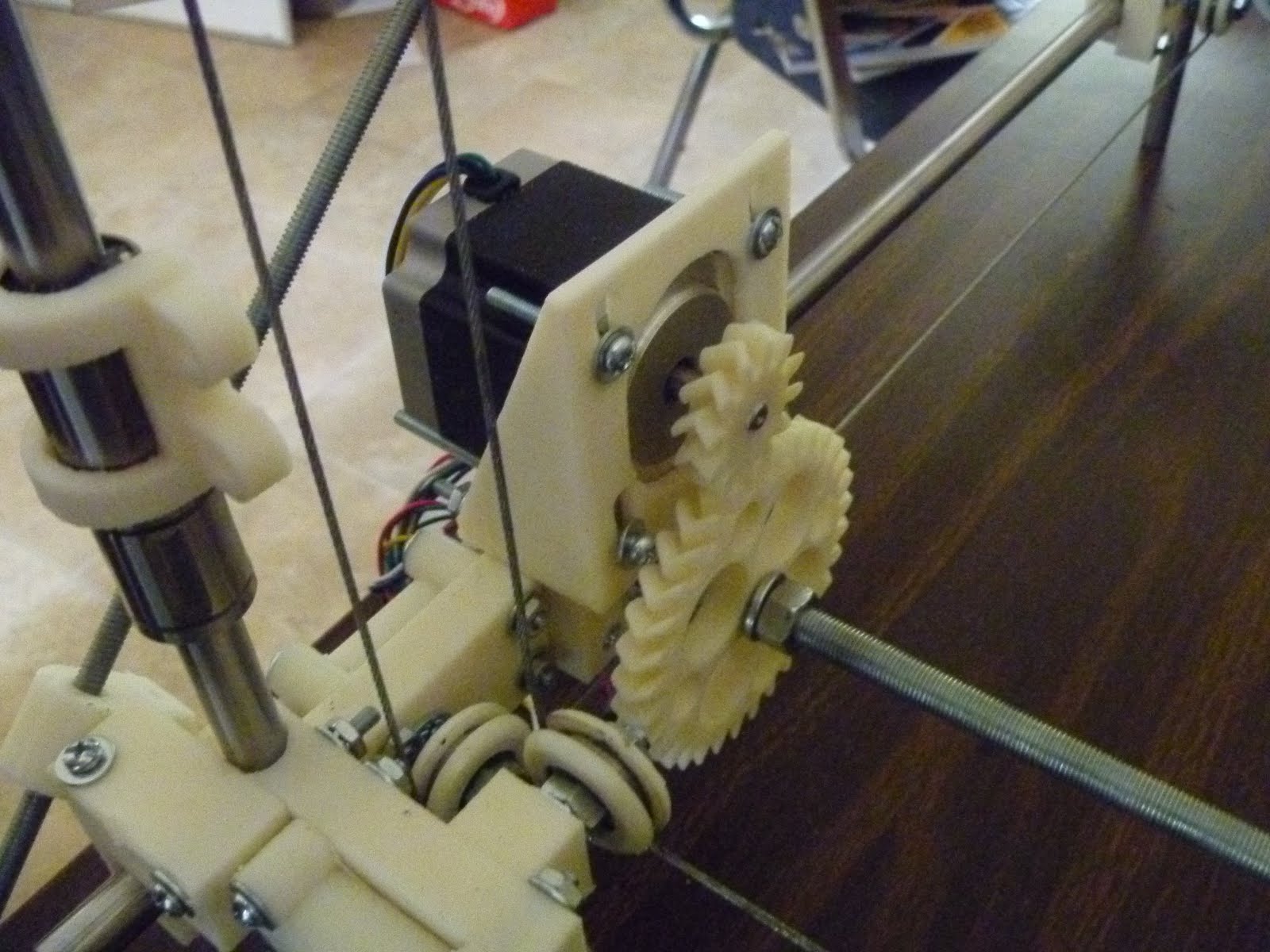
That milestone meant that I had to move Sampo into the front room so that firmware development could begin.


Sunday, May 22, 2011
A Z-axis gear set for the Sampo 3D printer
Few experiences are more satisfying than a creating a useful device of great intrinsic beauty


Saturday, May 21, 2011
Another battle in the string wars: cabled z-axis working
It took me 10 hours and fifty minutes to print the first print table bracket and I got a few measurements wrong, but it appears that the cabled z-axis concept is going to work.
Since the speed of the z-axis is not particularly critical, I intend to use a fairly high gear ratio between the NEMA 23 stepper and the lead screw that drives the cabling to insure that I have adequate force to overcome friction in the system.
Sunday, May 15, 2011
Refighting the String Wars.
Back at the beginning of 2006, before there was even a Darwin, eD Sells at the University of Bath was designing Darwin's predecessor, ARNIE. Confronting the problem of designing a z-axis, eD adapted the kinematics that were used on old wire cable parallel bars found on drafting tables.

eD adapted this technology in 3 dimensions to allow a single stepper motor to raise and lower ARNIE's print table.

Having trained as an architect before the Great Flood, I immediately fell in love the idea and adapted it to my failed Godzilla Repstrap design.

eD encountered no end of trouble with the cabling idea and eventually abandoned it for an approach which used four pieces of studding {threaded rod}.
It tends to be forgotten but the first fully operational Reprap machine at Bath was ARNIE, not Darwin. Indeed, Bath's traditional whiskey shot glass, the second one printed after Vik Olliver's in New Zealand, was printed on ARNIE. This approach was refined in Darwin.

Rapman, a Darwin derivative, was put into serial production by Bits from Bytes and is still selling quite well, today.

This z-axis approach does have its problems, though. Studding is most definitely NOT a proper lead screw. When you undertake to use four pieces of studding to raise a 3D printer's print table, the tendency of studding to be not quite straight plus the fact that you are using four pieces of not quite straight studding can lead to some unpleasant consequences. Here is an extreme example of what can happen.

If you expand the pic, you can see a nasty juddering of layers taking place. Here is a more usual example of the effect.

This is an extreme closeup with the light accentuating the effect. The object is quite smooth to the touch. The effect is still there, though. Here is a more usual picture showing the effect.
If you expand the pic you can see a regular pulse peaking at every seventh layer. This varies depending on how you adjust your machine and how straight your studding rods are. The closer the alignment, the better your print quality.
Now Bits from Bytes set out to solve this problem in their out-of-the-box BfB 3000 printer. They used a single proper lead screw to drive a cantilevered print table.

Both the Ultimaker and Makerbot's Thingomatic use the same approach.
Recently, when I decided to kaizen the old Darwin design, I decided to see what I could do about the z-axis situation. I didn't like the cantilevered print table approach and I did not want to simply duplicate the 4 studding solution originally used. That got me to thinking about the old cabling approach that eD had used back in 2006. The problem with it seemed to be applying force to the cable to move the print table. eD tried to use a friction wheel and eventually gave it up.
It occurred to me that it might be reasonable to use a single studding lead screw to apply force to the cabling. Lead screws can apply LOTS of force. So why not just attach one to the cable at a convenient point and be off?
I am in the process of doing just that.

I have circled the lead screw's thrust collar, the cabling turnbuckle and a linear bearing. Those three elements will be connected and a NEMA 23 stepper used to drive the cabling to raise and lower the print table.

Here you can see a detail of the cabling scheme associated with a pair of linear bearings on a vertical shaft. I have got to design a connector between the cable, the linear bearings and a corner of the print table. Hopefully, this approach will let me get a smoother z-axis operation without the juddering so characteristic of the Darwin design.

eD adapted this technology in 3 dimensions to allow a single stepper motor to raise and lower ARNIE's print table.

Having trained as an architect before the Great Flood, I immediately fell in love the idea and adapted it to my failed Godzilla Repstrap design.

eD encountered no end of trouble with the cabling idea and eventually abandoned it for an approach which used four pieces of studding {threaded rod}.

It tends to be forgotten but the first fully operational Reprap machine at Bath was ARNIE, not Darwin. Indeed, Bath's traditional whiskey shot glass, the second one printed after Vik Olliver's in New Zealand, was printed on ARNIE. This approach was refined in Darwin.

Rapman, a Darwin derivative, was put into serial production by Bits from Bytes and is still selling quite well, today.

This z-axis approach does have its problems, though. Studding is most definitely NOT a proper lead screw. When you undertake to use four pieces of studding to raise a 3D printer's print table, the tendency of studding to be not quite straight plus the fact that you are using four pieces of not quite straight studding can lead to some unpleasant consequences. Here is an extreme example of what can happen.

If you expand the pic, you can see a nasty juddering of layers taking place. Here is a more usual example of the effect.

This is an extreme closeup with the light accentuating the effect. The object is quite smooth to the touch. The effect is still there, though. Here is a more usual picture showing the effect.

If you expand the pic you can see a regular pulse peaking at every seventh layer. This varies depending on how you adjust your machine and how straight your studding rods are. The closer the alignment, the better your print quality.
Now Bits from Bytes set out to solve this problem in their out-of-the-box BfB 3000 printer. They used a single proper lead screw to drive a cantilevered print table.

Both the Ultimaker and Makerbot's Thingomatic use the same approach.
Recently, when I decided to kaizen the old Darwin design, I decided to see what I could do about the z-axis situation. I didn't like the cantilevered print table approach and I did not want to simply duplicate the 4 studding solution originally used. That got me to thinking about the old cabling approach that eD had used back in 2006. The problem with it seemed to be applying force to the cable to move the print table. eD tried to use a friction wheel and eventually gave it up.
It occurred to me that it might be reasonable to use a single studding lead screw to apply force to the cabling. Lead screws can apply LOTS of force. So why not just attach one to the cable at a convenient point and be off?
I am in the process of doing just that.

I have circled the lead screw's thrust collar, the cabling turnbuckle and a linear bearing. Those three elements will be connected and a NEMA 23 stepper used to drive the cabling to raise and lower the print table.

Here you can see a detail of the cabling scheme associated with a pair of linear bearings on a vertical shaft. I have got to design a connector between the cable, the linear bearings and a corner of the print table. Hopefully, this approach will let me get a smoother z-axis operation without the juddering so characteristic of the Darwin design.
Subscribe to:
Posts (Atom)