Saturday, August 28, 2010

Making a lid for a potentiometer mounting box


In which your narrator shows you a few tricks of the trade with thin-walled prints.


In my telepresence robot hand project I'm not using off-the-shelf servomotors but rather making them from scratch. A servomotor basically consists of a gearmotor, a potentiometer and some electronics, in my case an MCU.

You saw in my previous posting how I'd developed the hand segment and sorted out the gearmotor positioning therein. That done, I had to turn to see to mounting a potentiometer. I decided to simply add an extension to the back of the hand segment to contain the potentiometer.

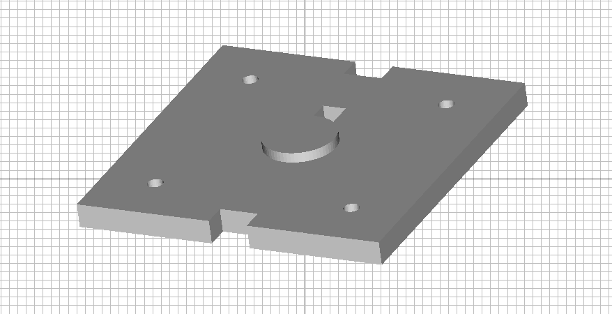
I'll not go into detail about the design of the box itself but rather cover the trick one uses to design the lid for the box. Here is the box.

The mounting box is nothing special.  It's a simple square box with mounting rack groves in the sides, seating for the potentiometer and screw posts to secure the lid.


The box is simple to design.  It took me about seven design iterations to make everything fit properly and to get the proportions worked out.  Using the Reprap 3D printer at every step meant that it was a very low risk exercise.

The box itself in Art of Illusion 2.8 was a simple box in which I'd removed the mounting slots on the sides with two boolean ops.


Once that was done I simply removed the voids where the potentiometer would be seated and where the mounting screws would be fitted.  I've switched Art of Illusion over to wireframe mode so that you can see the voids since they don't penetrate the surface of the mounting box.


Designing thin walled parts is a bit like designing an old photographic negative.  You design the  skin of the object and the holes inside of it rather than trying to design the object itself.  When you print the object you simply don't use any infill.  The top of the box is just another kind of infill, so it is omitted, too.

Here you can see how the printed box seats the potentiomenter.


Now, designing the lid you simply take the Art of Illusion file for the box and leave out the void that seats the potentiometer.


You want the lid to have holes that match the screw posts in the box so you leave those voids in.  

Next you slice off the top of the box leaving the screw hole voids exposed.  You do this in Art of Illusion by simply creating a block and merging it with the top of the box down to where the screw voids begin.


Then you remove the top of the box using Art of Illusion's boolean ops function.


While you don't want to have a hole big enough to slip the whole potentiometer through, you do need to accommodate its shaft.  A simple way to do that is to simply take a copy of the seating void cylinder and put it back into the object as a solid rather than a void.


Since we've sliced off the top of the box you can see the top of the cylinder now.  Now it's just a simple matter of reducing the radius of the cylinder to a bit more than the radius of the protruding shaft.


Now do a boolean op to remove that cylinder so that you there will be a hole in your lid.


When I looked more closely at the potentiometer I noticed that there was a little metal tab on one side to act as a stop to keep it from rotating around its shaft.  I had to design a little slot into the lid to accommodate that tab.  I did that by simply locating a little block where I wanted the slot to be.


Then I did a boolean op to remove the space occupied by the block.


At that point I brought back the cube I used to slice off the top of the box and moved it down so that exactly the thickness of the lid was exposed.


I then did a boolean op that chopped off the bottom of the box so that only the lid remained.


At this point I discovered that I'd made a mistake.  I'd designed the hole in the lid so that it fit the shaft.  Actually, the shaft fitted into a seating hub in the potentiometer that stuck out about a millimeter.  I brought back in the shaft cylinder that I'd used a moment ago and widened the radius to a bit over the radius of the hub.


I then removed that cylinder via a boolean op which widened the hole to accommodate the seating hub.


Now comes the tricky part.  The lid as designed will sit on top of the box.  I want it to recess into the box.  I could try to do this using Art of Illusion, but there is a much simpler way much less likely to fail.

Remember that the box will be printed without infill.  In this particular case we will print it with two 0.8 mm print roads describing the perimeter with a thickness of 1.6 mm.  Print roads tend to be rounded on the inside of the box, a fact that makes working them with Art of Illusion a bit messy.  It is easier to just process the  lid in Slice and Dice.

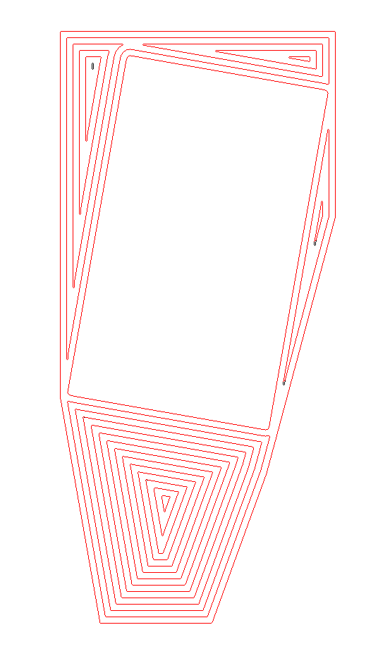
Once you've done that you simply go into the Filled folder and pull out the image of the print roads for the lid.

In the present state of development of Slice and Dice with complex prints roads like this it is necessary to go in with Windows Paint and clean up the print road image a bit.  Here you can see a few flaws in the roads image.


I've circled two of the most obvious.  In the upper right hand circle we have a feature that is less than 1 mm in diameter.  The lower circle encloses a loose print segment that is too small to print.  It's best just to remove those in Paint.  You will also, when inspecting the print, note that several of the print road loops are broken by a missing pixel or have tags of pixels hanging on.  Those should also be fixed or removed.

You usually only encounter this kind of problem on slices with very complicated print roads.  That's not a big deal and it is a quick thing to fix in Paint.  Since Slice and Dice processes images rather than arrays of numbers at each step you can go in and make changes with Paint if there is some flaw that you want to fix.  You can even alter the print roads in Paint if that suits you.

Altering print roads is exactly the trick we will be using to make the lid recessed.  The box has a perimeter of two print roads.  We simply go into Paint with our lid and erase the outer three print roads.

That lets the print box lid fit into the box and sit atop the screw posts inside.  We could have simply removed two.  In practice, however, that requires a bit of touching up with fine grit sandpaper on the edges to get the lid to fit.  Removing three roads leaves a 0.8 mm gap between the box and the edges of the lid.  That's good enough for this job.

Here you can see the potentiometer box with the newly printed lid lying beside it.


Now you can see that the lid fits nicely over the potentiometer.


After that it's a simple matter of securing the lid with metal screws and putting on the potentiometer's washer and nut to complete the job.


Now you check the fit between the potentiometer box and the hand segment.


You are now ready to connect your potentiometer box onto the back of the hand segment with boolean union ops in Art of Illusion and then print out the resulting large part.

This is how you create a large complicated part by designing it as a set of smaller, simpler parts.

Wednesday, August 25, 2010

Designing with a Reprap machine in the loop


In which your narrator celebrates a return to craftsmanship made possible with the addition of a Reprap printer into the design process.


In the five years I've been on Reprap team I think that possibly the most terrifying and depressing transition of the many I've made during that time was actually having a 3D printer on my worktable and having to face up to turning some of my pipe dreams into physical realities.

Let me tell you, it's a lot easier to dream up something than to actually cobble it together and get it working.

To begin with I had discovered that thin-walled prints tend to be quite strong, properly designed, and don't have nearly the trouble with warping that we've had with large, filled objects.

For a project I wanted to create an animatronic hand for a telepresence robot project I've wanted to undertake for several years now. If you go out to and buy one you're looking at anywhere from $5-50K for one hand. I haven't got that kind of money so I dug around on the internet till I found a guy in Indonesia who'd made one for $300 in parts.


Andreas Maryanto's  approach is both brilliant and cheap.  I used his project as a starting point and was able to use his blueprints for getting proportions and sizes right.

 I was also impressed with the Meka Robotics hand design.


Meka's hand was expensive, but had several interesting points.  It was self contained and used elastic bands to return the hand to an opened position.  I liked that.

I started small, with a fingertip.  Actually, half of a fingertip.  I did the design with Art of Illusion 2.8.  AoI has always been about the easiest to learn, free 3D CAD app around.  With the introduction of version 2.8 the problems with the boolean operators have been largely solved.


While AoI 2.8 will, occasionally, create a flawed STL file, these can be easily repaired in the free Netfabb Basic app.  The combination of Art of Illusion and the free Netfabb app, now available on the cloud as well, makes for an extremely powerful combination.

I wanted the joint between phalanges in the finger to be integral with the print, that is, not requiring any additional hardware. I printed and worked with the finger tip for quite some time.


Eventually, after a few dozen prints and redesigns, I got it to do what I wanted.


After that, the rest of the finger came together rather easily.


So, I had the joints right, but how to integrate the actuating tendons was a puzzle.  Within a week or so I had a tentative solution.  I could incorporate slots in the phalanges of the finger to guide and protect the tendons.  This meant that I had to import the STL files for the parts back into AoI and carve out the slots to seat the tendons.  Here you can see the STL for the second phalange slotted.


After slotting the second, third and fourth phalange in AoI and reprinting them I had a tentative solution for flexing the finger.


At that time I used a single tendon running through guides along the top of the finger.  That was later to change.


I quickly explored using servos very much like the ones Andreas had used.


...and just as quickly rejected them as overspecialised and too bulky for use in my hand.  From there I went on to creating my own servos from scratch using gearmotors and potentiomenters driven by a micro controller.

Once I'd settled on a gearmotor that I had a supply of...


...it became a matter of designing a section of the actual hand and accommodating the gearmotor inside.


Notice that the design of this part is only aiming at holding the outline of the gearmotor and providing a recess for the finger.  The goal is to work out the seating of critical parts and getting the general shape of the part right before trying to accomplish more.


At that point, I needed two finger assemblies to get a feel for the clearances and volumetrics between finger ensembles.


Attention to the reel that would wind up the tendon that contracted the finger was the next step.  I'd decided by this time to use a Meka-style elastic band on the top of the finger to return it to the open position.

The reel was a tiny, finicky part, given the clearances in the hand section.  I printed two of them at a time to avoid having to do a lot of pausing for the reels to cool between printed layers.


That done, I needed to do a bit more work with the hand section.  First, I needed to seat the gear motor.  The hand segment was a big, rather complicated part, so rather than trying to redesign that I simply designed a plate that could be glued onto it that would achieve the effect.


By this time I had slotted the reel to make attaching it to the nylon tendon easier.


While I glued that gear motor support plate to the hand section, I could just as easily do a boolean union in Art of Illusion between the two parts and print them as a single part, or not, as convenience dictates.

From there, I designed a housing for the potentiometer that butted onto the base of the hand section.  You can see it on the left-hand side of this picture.


Notice how I haven't bothered gluing this part to the bottom of the hand segment but rather just clamped it.  I've not settled on all the dimensions and placement of this part yet, so gluing isn't justified.

Similarly, you can see here that I just took the hand section into the free Netfabb app and flipped it into a mirror image as a start towards completing the hand segment.


The point of all this is that you can take on some really challenging design exercises if you will just take them a little bit at a time.  Having a Reprap 3D printer {in my case a Rapman 3.0} makes it possible to print out a partially designed part and try to match it up with the bits that go in it and the bits with which it must integrate.

While you can do all that in a 3D CAD system you have to have a very good sense of volume and space to do so.  With the Reprap printer in the mix, you don't have to be that good.

Don't be afraid to use filament during the design process.  You're not wasting it.

Sunday, August 22, 2010

Cloud CAD


Ordinarily, I publish only my own work on this blog. In this particular case, however, I'd like to pass along a nascent project to make OpenSCAD available in a computing cloud environment.

Tony Buser is the man on this undertaking. It's a very worthy one, imo.

Thursday, August 19, 2010

Introducing Snakl!


He used to live on Tommelise 2.0 but recently took up residence on my Rapman 3.0...


Snakl does all the hissing!  :-D

Chasing bugs in Slice and Dice


I had completed my narrow profile telepresence finger and then set about designing a mount for the gearmotor and potentiometer to drive it. The mount came out looking a bit weird.


Trust me, though, there were good reasons why it took the shape that it did ...  in my twisted mind, at least.

The first thing I discovered was that my print roads routine is not extremely happy with sharp ended print roads like you see here.


Fortunately, I was able to pull the few unique slice images into Windows Paint and clean them up rather handily in just a few moment.  Slice and Dice is very good about giving you ways around problems you encounter with difficult parts.  The messy print roads were only the beginning of my troubles, however.   When I tried to turn the image into an XML description of the roads all hell broke out.  My pathfinder routine, which worked well enough for most slices, really hated this gearmotor mount.

I finally gritted my teeth and spent the time chasing up the many bugs in the pathfinder routine.  Once that process, which took about two man-days, was complete, I was able to get a pretty good XML conversion.


Red overlays indicates well formed print roads.  The black residue shows where the routine failed.


You can see the failures circled in blue.  Looking a bit closer at a few of the failures you can see that the routine breaks down when the distance between two parts of a print road drops below 0.2 mm.  That's a ridiculous case, but slice and dice routines regularly encounter ridiculous cases.  Here is a typical one.


Here you can see that the pathfinder routine jumped the 0.1 mm gap between two sections of the path.  Another thing that became obvious is that the routine can't handle paths which are less than 1 mm in their greatest dimension.


None of these faults are serious enough to cause me to continue working on the code at the moment.  I'm back to printing.