Sunday, February 28, 2010

Slice and Dice 0.1


Last month, Adrian incorporated some ideas for using pixel maps that I'd used years ago with Tommelise 1.0 into what I understand is his most current version of the Reprap host software. At the time I was happy that my approach had proved to be of use to him.  I was, however, happily using Skeinforge with my Rapman printer at that time and didn't think too much about it.

Enrique's Skeinforge is a brilliant piece of software for non-mainstream Reprap printers like my Rapman.  As is my wont, however, I tend to test the envelope with just about any piece of hardware or software that I undertake to use.  The problem with testing the envelope is that too often you push right through it.  That happened to me when I started trying to print light, open structures like this.


Enrique invariably handles error notifications within a day or two.  I frankly don't know how he manages.  It must require superhuman capabilities for one person to manage that for so many users.  What I was trying to do, however, wasn't eliciting what could be termed an error as such.  The individual slices for what I wanted to print were quite small.  As a practical matter, what that means is that is that the layers tend to overheat from the extruder tip being over them too long on average.  Let that go on long enough and you wind up with a print that looks like a melted candle.

Skeinforge has a "cooling option".  What it does is time how long you are spending printing a layer and if it falls below your set point it orbits the extruder tip around the print till it has a chance to cool off.  Thanks to the tendency of extruder tips to dribble ever so slightly, if you use this option your print becomes wrapped in what looks like plastic cotton candy.  It is a bear to clean parts wrapped up like this.  The other way that I developed when printing small pinion gears was simply to print 6-8 of the same thing at once, something that Skeinforge lets you do very easily.  While that is very handy if you need a lot of a thing, if you're just trying to develop a part you take 6-8 times longer to print your part and find the errors in the design.  With ABS costing $10/lb using Skeinforge's multiply option is not a very practical as a cooling method.

I finally came to the conclusion that Skeinforge, as it presently is written, wasn't going to take me where I wanted to go.  I had ordered a copy of the new Netfabb programme to do the same thing, then learned that their product rollout was going to be at least a month late {1 March}.

With several weeks of time on my hands, I decided to dust off my old Slice and Dice software and see if I could knock it into shape to do what I wanted.  Three weeks later, it's running.


Let me tell you from the beginning that Slice and Dice 0.1 is most definitely NOT an alternative to Skeinforge, Netfabb or the Reprap Host software.  If you are thinking that, forget it.  Now I'm not trying to keep anything proprietary.  If you want the source, I will give it to you under a BSD-type license which lets you do pretty much anything you want with it.  Indeed, I've handed out several copies already to a few reprappers who wanted a look at this or that bit of the code.

Before you decide you want it anyway, however, here are some facts about it that you should be aware of.

  • It is written in Visual Basic .NET {the free Express 2008 edition}
  • It is Windows specific
  • It is NOT beta code.  I'd have a hard time calling it alpha code at this point.
  • It is set up to handle only one print object at a time.
  • It keeps multiple bitmap images {BMP} of each slice.  These are 250x250 mm with a 0.1 mm resolution {figure 22.5 megabytes per image.  All the processing is done on images that you can look at.  What that means is that a decent design is going to generate many, many gigabytes of images.  I don't care since I have a 1 Terabyte external disk committed to the programme.
  • I will NOT provide support for Slice and Dice 0.1.  If you take it you're on your own.  I admire what Enrique is doing but do not envy his situation and most definitely do NOT mean to in any way compete with Skeinforge and Enrique or Reprap Host and Adrian or the good Germans who are fielding Netfabb.  I'm not young and life's too, too short.
I've put Slice and Dice 0.1 together for one specific reason.  That is to let me try out off-the-wall 3D printing ideas that often times will go beyond the capabilities of ordinary software.  Most importantly, its a piece of software that I've written and can easily dive into myself and fiddle with to make it do new things without having to report problems to and make requests from others.  I figure it will save me a lot of development time by shortening the development cycle.  It for sure will keep me from making a pest of myself making requests for changes in their code to Adrian and Enrique.  That should be good for everybody's nerves.

Putting a lid on it


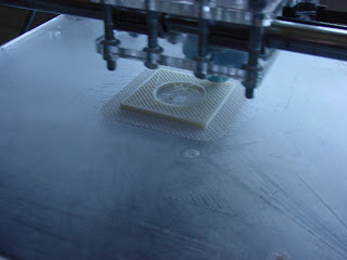
I was able to shuffle around image files and, starting from the top of the slices {a "sky" slice that is taken above the print object} find which parts of the print object need lids {closed infills}. Here you can see an earlier test print showing the cross-hatched infill.


This pic shows the infill print in progress this morning.


The lid(s) on a print {depending on the complexity of the object there may be many} are taken in several layers by smoothly closing the infill down in several layers till you get a complete seal for the lid itself.  Here you see the first layer of the closing of the infill being printed.


Here the lid is closed completely.


Note that I still have some work to do to get the infills and lid to mate properly with the perimeter  Finally, you can get a better look at the print quality of the object removed from the printer.


Slice and Dice, as a personal research tool, is basically operational now.

Saturday, February 27, 2010

Sorting a few things out


I had a bit of code cleaning to do to prepare for putting tops and bottoms on a infilled solid.  Of course, it took longer than I expected.  All the same, it's done for now.  I was able to run a 5 mm high exercise this afternoon.


You can see with this skirt routine that when I specify a 10 mm skirt, you get a 10 mm skirt.  Note the hole in the middle of the raft.


I've got some additional code to put in to convert extrusion/head speed rates into widths and depths of print roads automatically.  That should cure the gaps between the infill and the perimeters.  Right now, I am doing thumb sucks.  I'm getting pretty close but not spot on.


Friday, February 26, 2010

First collated print


Slice and Dice processes perimeters, infill and the raft separately as gcode.  Because of that, to create a print file of gcode I had to write a collation routine.  That was fairly straightforward.  Here is the first print of a test block with a cylindrical hole in it 2.5 mm thick with a cross-hatched infill.


The next task will be to write the code to put solid tops and bottoms on objects.  I'm processing a 5 mm thick version of this test block to give me enough layers to be able to do that without a lot of drama.

Thursday, February 25, 2010

Doing prints


I had to go back and do some cleaning up in the raft generation coding. Mostly that entailed porting the latest infill code from the object infill back to the raft. Integrating the raft with the infill print was trivial. I keep the perimeter and infill xml in separate files for each layer, so doing a print is largely just a matter of shuffling files.

The first exercise I did was to print the raft first and then print the infill of the object on top of it.


The infill stack was 2.5 mm thick.  I've never been able to understand why Skeinforge prints such a heavy raft so slowly when for the Rapman extruder printing at high speeds and high polymer flows is a snap.  I printed a two layer, 0.25 mm/layer thick raft at 16 mm/sec.  It stuck quite nicely.  I then went on to print the infill on top of it a few minutes later with no problems.

Just for fun I popped the perimeter for the object that I'd printed at lunch over the infill.


It was a bit of a tight fit, not being welded to the infill during the print, but it reassured me that I hadn't got the overall sizes wrong in the analysis..  I will see if I can integrate the perimeter into the object print in the morning before I do my day job.

Perimeter vectorisation code done for now


I was able to fully test the perimeter vectorisation code at lunch today.  Here is the test print.


The infill, done earlier, is to the upper right of the perimeter print.  I left the extruder on when the print moved from the outer perimeter to the inner so that the two parts would stick together.  I've found that photographing white ABS print on a sanded acrylic print surface on the Rapman gives you a very low contrast pic which is a pain to read.  Putting white ABS on a wood veneer background photographs very well, on the other hand.

I set the extruder to print a little thick so that it would stick to the print surface without a raft.  The outer perimeter is 2 mm wide.

The vectorisation code produces pretty smooth, fast gcode.  It is not perfect but it will do for now.  The next step is to integrate the code modules which process the perimeter and infill.

Wednesday, February 24, 2010

Getting the perimeters right


When using a image processing approach to slicing and dicing when one extracts the perimeter of a curved boundary one is faced with an avalanche of very short (~0.1 - 0.1414 mm) print segments that do not easily transcribe into nice long, straight print roads like infills tend to. Trying to print 0.1 mm line segments presses the limits speed at which the Rapman MCU can take data off of the SD card and process it into stepper instructions.

I spent several days reasoning that if the conversion of vectors into bitmaps is rasterisation, then I ought to be doing the reverse process which is vectorisation. Vectorisation is a well-understood, if unpleasant algorithmic process. After struggling with the likes of the LZ78 algorithm for several days, I finally realised that what I needed to be doing was far simpler than that.

The approach I've finally taken was quite simple. My routines identify a series of pixels that form the boundary of an object slice. I simply begin by taking the first and third pixels in the path and forming a line thereby. Once I have this line I then determine the normal distance of the second pixel to that line. If it is less than a boundary that I can set I go on to test pixels one and four as a line and check the normal distances ob two and three against the the boundary value. I continue that process until one of the internal pixel's distance exceeds the boundary. I then step back one pixel and save that as the end points of a line segment in the compressed boundary. I then repeat the process using the end point of the last line segment in the boundary as the start point for the next until I've finished with the whole boundary description.

What I've described is a classic smoothing algorithm. The larger one sets the boundary the larger the degree of smoothing the boundary will be subjected to. I typically set it to 0.05 mm at the moment.

The code seems to handle my circular boundary problem adequately for the moment.

Sunday, February 21, 2010

Improving the infill routine


I decided to separate the infill and perimeter routines. The main reason for doing that was that I found that with image processing of objects you tended to get a more detailed, almost fractal description of perimeters than you do with a geometric slice and dice routine like Skeinforge uses. What that means is that the apparent speed of the extruder head doing perimeters is much slower than it would be with Skeinforge simply because the perimeters are described with many more, very short (~0.2-0.3 mm) line segments.

I quickly found that that requires closer control of the extrusion rate than would be the case with Skeinforge. I made some headway on that problem on Saturday, but by no means am I finished working on the problem. It was obvious that infills, composed of line segments maybe a magnitude bigger, did not require the close attention that perimeters do. This led me to separating the two kinds of extrusion roads, a task that took most of Saturday.

Once that was done, I turned my attention to infills and created a little bit harder test exercise.


I then started doing test prints of just the infill.  It quickly became obvious that my quick and dirty end-to-end approach to reducing the distance between extruded roads on the infill was not going to be enough.  That simple method simply took a infill line segment and looked to the next on to see if the line could be reversed to  reduce the time between extrusion.  While that helped a lot there was still a lot of stringiness happening because the sweep method I used for identifying infill line segments didn't necessarily put them in proximate order.

Today, I decided to rewrite the end-to-end routine to put the infill line segments into as close a proximate order as possible.  It was a very frustrating exercise that finally came right a few minutes ago.


The left infill print uses the end-to-end approach.  You can see that the sweep method of identifying line segments leads to a lot of jumping back and forth between the sides of the hole in the block.  My new proximate approach, seen on the right, reduces the need for long distance jumps to virtually nothing.

It really is an advantage, having a printer to test your code against.

Stumbling across the biopolymer zein


It is hard to find time to hare after all of the potential research directions implicit in the Reprap undertaking. As a result of that, I've tried to concentrate on just a few areas dealing with the increase of the printed percentage of Reprap machines. Yesterday, however, I got off-track for a few hours.

For some reason I found myself looking for the Wikipedia entry for bioplastics and serendipitously keyed in biopolymers instead. There, I ran across a reference I hadn't seen before about a biopolymer called zein.  The article referenced an incredibly detailed review of the material concentrating on its extraction written up a few years ago by John W Lawton at the USDA laboratory at Peoria in Illinois.  Apparently, there is a large collection of zein related articles there which served as the basis of Lawton's extensive article.  A few things about zein jumped out at me.

The biggest was that it was a protein, biopolymer which used corn gluten meal, a rather useless byproduct of the corn milling process.  Corn gluten meal is a non-nutritive waste product that is typically used as a bulk agent for cattle fattening.  It also has developed a small reputation as an "organic" herbicide for home gardens.  This last is important because it means that 50 lb sacks of it can be had by ordinary people in one-off quantities at prices of under $1/lb.  What that implies is that corn gluten meal is basically free and that what you are looking at is mostly the packaging, warehousing and transport cost when you purchase it.

The second was that reading over the Lawton article that the most successful extraction methods were achieved with kitchen chemicals {rubbing alcohol with a touch of lye} and chemistry.  As well, zein has a long history of being used as a plastic, coating and, interestingly a fibre.  This last I will talk about a bit later in this blogging.

Zein was used extensively before being displaced by petroleum-based substitutes during the 1950s and 1960s.  Currently, ready-to-use zein is quite expensive {~$10-25/lb} not because of its intrinsic cost but rather because its very limited market, viz, food grade coatings for pills and food products commands such prices due to its highly regulated nature.

I vaguely remember from my childhood a wool substitute fiber called Vicara which emerged in the 1950s before being replaced by synthetic, petroleum-based fibers a decade or so later.  What shool me about the Lawton article was that Vicara was made from zein.  The rather high softening temperature of Vicara {~245 C}.  If the melting temperature of zein is anywhere near this a whole range of products like coffee makers and the like become possible.  Using PEEK instead of PTFE for thermal barriers in extruders, something that we are already beginning to do regularly, ought to let us get by with that.

Oddly, zein's glass transition temperature is very low {~40 C}.  It may be that like PLA, zein has no real warping problem during printing compared to petroleum-based polymers.

Heretofore, our use of plastic filament as feedstock for printing has caused practical problems when mapped against our desire for a recycling scheme for plastic.  With recycling we have to grind the waste plastic, a problem that appears to have been solved recently.  Afterwards, we have to extrude the filament.  The machinery for doing this extrusion is relatively complicated.  Sadly, you can't just extrude filament.  After it is extruded you have to quench, reheat and run it through a series of godet stations before you can spool it.  This videoclip gives you a fair notion of the complexity and scale of the process. It seems to me that scaling down that sort of process is going to be an undertaking much more complicated than the Reprap printer

The notion that zein was made into fiber coupled with the application of electrospinning to zein fibres led me to quite a new idea.  What would stop us from using spun fiber instead of monofilament in our extruders?

Electrospinning can be achieved with very simple apparatus such at this piece of lab equipment made in New Zealand.


Spinning the filament into thread of the proper diameter is an old, old technology easily scaled to our application.  This Indian charkha shows how simple the technology can get.


Filament is useful in our extrusion technology because it is stiff enough to be forced into our extruder barrel under pressure.  Obviously, fibre thread can't.  Keeping in mind, however, that our thread is polymer, we should be able to draw it through a heated die to consolidate the fibres into a single polymer mass.


Thursday, February 18, 2010

End to end


I wrote a routine that serially checks paths and reverses them, if necessary, to minimize the travel distance between one path and the next.  Basically, I look at the end points of each path, then print the first path and compare its trailing end with the end points of the next path. I then choose the nearest one.  If it is the leading point then I print the path as is.  If it is the trailing point, then I reverse the path and then print it.


As you might imagine, it greatly reduces the print time and makes for a much cleaner printed raft.


I now have all of the routines running more or less properly to print objects.  That comes next.


Sunday, February 14, 2010

Got the perimeters going


I wanted to do a direct translation of my XML format to gcode instead of breaking it into perimeters and infill as I had it before. The way I did it previously worked fine as long as you only wanted the possibility for one kind of infill. I'd like to a little better than that this time.


I've got a bit more work to do getting the ends of the infill to match a little better with the perimeter, but for now it is working pretty well. The brown bits are fried ABS that fell off the extruder head.  I should have cleacked to see that it was clean before starting the print.

You can see a little misalignment of the perimeter of the raft. It turned out that the grub screw on the stepper side of the y-axis had shaken loose. Fifteen minutes of fishing around in the pocket in the acrylic assembly that it had fallen into with a hemostat recovered it. Once reinstalled, the misalignment disappeared. :-)

Saturday, February 13, 2010

The raft {infill module} works


Luckily, I was able to isolate the alignment problem to a loose y-axis belt pulley.


You can see that the alignment is perfect this time.  The missing bit of print path happened because that path was the first one printed and the printed filament broke loose for about a centimeter from the point of first contact.

Now, on to checking out the module that does the perimeter.

It's rude, it's crude ...


... it's socially unacceptable. Slice and Dice is my code, however, and when I want to try something new I can just dive into the code without having to ask anybody anything.

I've got to the point where I'm testing parts of the gcode generation on the Rapman.


Right now, I'm doing test prints for a fitted raft for a small, rectangular block.  As you can see, I have a problem with the alignment between the two layers of the raft.  The roughness of the second layer is happening because I haven't got around to arranging the print roads end-to-end yet.  Sorting out the alignment comes first.

I've also tried printing out a few layers of the block itself.  I've got a bit of trouble with the perimeter which I hope to get sorted out later today.

Having a printer sitting next to the PC I'm developing the Slice and Dice code on that can test code changes in a matter of a few minutes is a real blessing.

Monday, February 08, 2010

The latest and greatest from Skeinforge


Skeinforge continues to exhibit bizarre behaviour when you use the multiply feature.

All that was changed between these two runs was the number of the same item being printed. The one on the left printed 2 beam segments while the one on the right printed four.

Saturday, February 06, 2010

Testing the envelope


This has been a pretty frustrating week.  Last week I got a long way towards evolving a thin-walled approach to making post-tensioned, composite structures which could support herringbone rack and pinion systems.  This week I wanted to push the post-tensioned theme a bit further and decided to see what issues were involved in printing an open structure beam/column system.

For a first pass, I developed this stackable, interlocking beam module.


It was a bear to create with Art of Illusion, but with Netfabb to clean up AoI's nasty STL files I managed, finally, to make it happen.

I did some preliminary partial prints to see what the issues were and discovered that I could either print one segment using the Sleinforge cooling option and wind up many hours later with a column segment that was festooned with strings of ABS ooze OR I could print several in the same time which required much less after-the-print cleanup.

That is when the trouble started.  In the several days prior to this exercise I'd discovered that I could print the column section for the herringbone rack at 32 mm/sec without a serious degradation in print quality.  This made printing these beam segments much less daunting a task.  When I began, however, I ran into a nasty concatenation of disasters that pretty much ruined my printing week.  The first one occurred when I started a print and shortly after was called away for about 45 minutes to help my sister install a new wireless printer she'd bought.

When I returned to the lab I discovered that my Rapman 3 had partially reset whilst printing the raft for the segment leaving the extruder running.  This unfortunate situation burned a small pit in my print table and buried my Kapton tape extruder head in a big blob of molten ABS.  The Kapton tape extruder head had been happily running since October, I believe, without complaint.  Being buried in ABS, however, pretty much put an end to it.

Fortunately, I'd bought several of BitsFromBytes new pre-made, silicone covered extruder heads.  After about an hour swapping out the old, ruined head for the new one I was printing again ...  almost.  There was, of course, the usual running in of a new part.  The new head was about 3 mm shorter than the old one, so I had to go through the whole adjusting for the new print height thingy, complete with printing new trial rafts and the like.

That done, I went back to trying to generate a set of four of the beam segments with Skeinforge.  Months ago, I'd downloaded the latest release, August's.  Skeinforge these days is a busy, overcomplicated piece of software which has far too many bells and whistles hung off of it.  In concept and execution, however, it is a brilliant piece of work.

That said, my column segment exercise pushed right though Skeinforge's performance envelope.  It appears that when you create a BFB file with more than a million lines of gcode in it, that the August version of Skeinforge simply runs out of memory and blows up in the Export routine.  After several false starts I finally got the most recent release of Skeinforge down and sort of working.  The memory problem was gone, but in its place was a total buffet of new bugs relating to both the Multiply option and the Speed option.  The two options appear to interact to produce some really bizarre gcode.

I'd hoped by now to have the new Netfabb gcode generator.  Sadly, the Netfabb people have discovered that the developing of that app was a bit bigger task than they'd originally thought, so the release date got pushed back from 1 February to 1 March.  That left me with either going back to my old copy of Skeinforge and limiting myself to the sorts of objects that it could process or sitting on my thumb for four weeks and hoping that Netfabb's revised release date didn't slip again.

There had been a prior bit of frustration back in November that pushed me into reviving my old Slice and Dice software app from the Tommelise project,  I had actually got pretty far along with that before I was able to get past Skeinforge's nasty learning curve and was able to print acceptably using it.  I went back and looked at that.  Recently, Adrian confirmed that I was on the right track using a brute-force, pixel-oriented analysis instead of the more conventional geometric approach.  Of course, my code is hideously slower than Adrian's, an understandable situation considering that he has been doing this kind of thing for his whole career.  :-)

Still, when I sat down and thought about my situation, I realised that it is in the nature of who I am that if I'm given something I will inevitably test it to its limits.  I always try to make things do things they weren't intended to.  That's just the Scots-Irishman in me, I suppose.  Given that situation, it's very dangerous in a way, to be dependent on equipment and methods that one can't get into and tinker with.  When Skeinforge crashed on me it was suggested that I turn in a problem report on how I crashed it and wait for Enrique to fix it.

Enrique is fast at responding, but I am still too obsessive, now that I am trying to work with post-tensioned, printed structures to happily wait to see if he can easily fix the problem.  Indeed, I find myself not much wanting to even report the problem.

So ...  back to working on Slice and Dice.


Thursday, February 04, 2010

Skeinforge on a tear


Has anybody seen anything like this before?


Skeinforge processes the STL properly but crashes when it tries to export the BfB file.  I've had this happen a bunch of times now.  Oddly, if I lay the beams on their sides they process and export the BfB properly.  When I stand them on end, however, it crashes.

I've watched the job's progress half a dozen times on the Task Manager and haven't been able to see any consistent set of conditions which might be causing the crash.


Any insight into what might be happening would be greatly appreciated.

Monday, February 01, 2010

A stepper controller for the Delta Robot

Some time ago, Nophead {Chris Palmer} suggested that I use microstepping instead of gearing to get the resolution that I need in using the herringbone rack and pinion with the Delta Robot kinematics. I had hesitated because doing so got me into the surface mount Allegro controller chips. I could have used the standard Reprap controller board except that it is incompatable with my Pic-based controller.

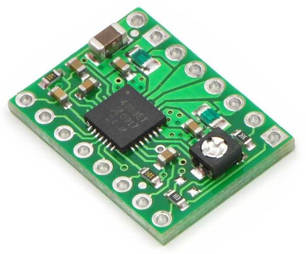
A happy solution presented itself yesterday. Pololu offers a breakout board equipped with an Allegro A4983 controller.


The A4983 is somewhat different than the A3977 that is standard in Reprap electronics in two ways. Foremost, the A4983 can handle a maximum current of only 2 amps instead of the A3977's 2.5. I don't find this compelling because in practice Repraps rarely require more than 1 amp in any case.

The winner for me is that the A4983 controller allows for microstepping down to 1/16 compared to the A3977's 1/8. While the A3977's microstepping is more than adequate for conventional Reprap machines I can use the extra resolution with the Delta Robot.