I had completed my narrow profile telepresence finger and then set about designing a mount for the gearmotor and potentiometer to drive it. The mount came out looking a bit weird.

Trust me, though, there were good reasons why it took the shape that it did ... in my twisted mind, at least.
The first thing I discovered was that my print roads routine is not extremely happy with sharp ended print roads like you see here.

Fortunately, I was able to pull the few unique slice images into Windows Paint and clean them up rather handily in just a few moment. Slice and Dice is very good about giving you ways around problems you encounter with difficult parts. The messy print roads were only the beginning of my troubles, however. When I tried to turn the image into an XML description of the roads all hell broke out. My pathfinder routine, which worked well enough for most slices, really hated this gearmotor mount.
I finally gritted my teeth and spent the time chasing up the many bugs in the pathfinder routine. Once that process, which took about two man-days, was complete, I was able to get a pretty good XML conversion.
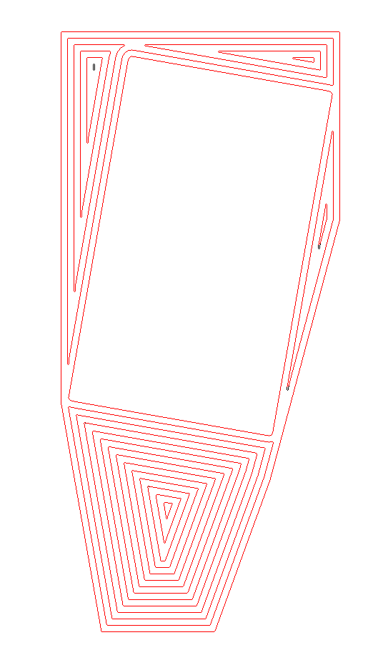
Red overlays indicates well formed print roads. The black residue shows where the routine failed.

You can see the failures circled in blue. Looking a bit closer at a few of the failures you can see that the routine breaks down when the distance between two parts of a print road drops below 0.2 mm. That's a ridiculous case, but slice and dice routines regularly encounter ridiculous cases. Here is a typical one.

Here you can see that the pathfinder routine jumped the 0.1 mm gap between two sections of the path. Another thing that became obvious is that the routine can't handle paths which are less than 1 mm in their greatest dimension.

None of these faults are serious enough to cause me to continue working on the code at the moment. I'm back to printing.
1 comment:
I wonder those acute angles might be better filled - once the outline is traced - by a serpentine path, or by cross-hatching (staggered across layers, if less density is appropriate).
Not sure where this intuition is coming from ... perhaps from when I used to do a lot of sketching? Manually filling in the tips of acute angles by tracing inside the outline got uneven results. Got better results from filling across.
Whether this applies to the present problem, I have no idea.
Post a Comment