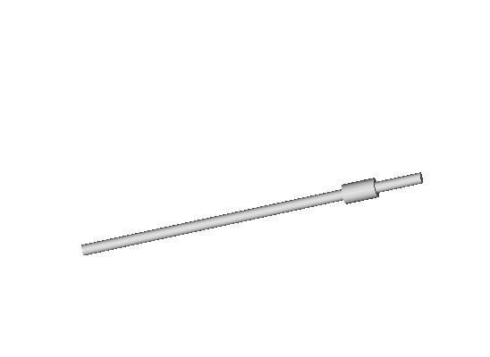
 First, I'm using a quarter-inch diameter wood auger bit that is just over seven inches long. It has eight flights in the screw for a length of four inches, two inches of bushing behind that and a shank that extends for an inch and a quarter beyond that. I didn't take time to develop the screw portion of the bit on the left on AoI and placed a thrust bearing where the bushing meets the shank on the right. The thrust bearing is made of a drilled out 3/8ths or 1/2 inch bolt.
From my previous experiments I determined that the auger should extend slightly beyond the end of the pumping section to preclude polymer packing in the pump barrel.  You can see the end of the auger extend just beyond the end of the connector plug that I've made from another one of those drilled bolts from which I've sawn off the head.
Now I include the body of the polymer pump. 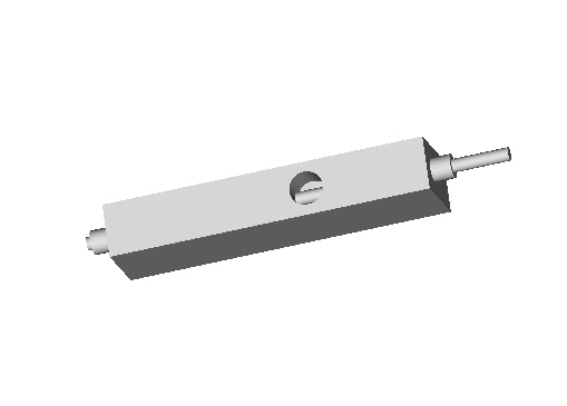 You can also see the polymer feed into the top of the pump and the feed chamber where it intersects with the auger.
  Next we screw the PTFE thermal barrier onto the connector plug. I've shown the PTFE bar, which has been drilled to a quarter inch to accomodate ploymer flow and tapped at each end to accomodate the connector plugs, as slightly smaller in cross section than it is so that you can see where the steel polymer pump section and the PTFE thermal barrier join.
We can now screw the heated extruder barrel onto the second connector plug seated in the end of the PTFE thermal barrier. 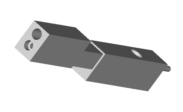 You can see that the heated barrel is drilled not only to allow passage of polymer as it is heated and is pumped towards the extruder tip but also to accomodate a 300 watt cartridge heater.
Now let us insert the cartridge heater. There is a quite inexpensive anti-lock compound that will prevent the cartridge heater from freezing up in its housing after a number of heating cycles. You will have to imagine the wires for the cartridge heater extending out the back of its housing towards the rear of the extruder. These cartridge heaters use regular lines electricity.You can also quite easily acquire bimetallic thermostats which can be used to control the temperature of the system. Like the cartridge heaters, these thermostats are very old technology and are also quite inexpensive.
  From this point we can apply the front and back retainer plates.
These are held in place by screwing the extruder tip into the heated extruder barrel on the front side and screwing the thrust bearing into the pump barrel on the back side of the assembly.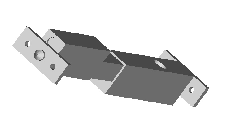
From there you secure the whole device with retaining rods made from threaded studding which are secured with lock nuts on both sides of the extruder.
This arrangement hopefully will preclude the extruder from coming apart from the internal pressure of some 40 atmospheres created by the pumping action of the polymer pump. I've calculated that this pressure will create an axial thrust of about thirty pounds.
Once that is done you simply add the feed funnel for directing polymer powder resin into the polymer pump feed chamber and you should be good to go.
I was going to use the gear motor for the Mk II, but decided that there was too much drama in accomodating such a small piece of equipment into what is a rather large (about 1 foot long and weighing 5-10 lbs) piece of equipment.  Using an electric screwdriver will, I think, make the question of securing the system to a mounting block considerably easier.
As for operating the system, I already own an infrared thermometer which will allow me to measure the surface temperature of the heated extruder barrel rather well. Initially, I plan to let the system heat up slowly whilst empty by adjusting the thermostat (which I will tap mount into the chin of the extruder barrel, not shown) until I get the temperature I want. At that point I will start the electric screwdriver and start feeding polymer into the system. The thermal capacity of the system is very much larger than the that of the polymer flow, so I doubt that the system will much notice the polymer being extruded from it energetically.
This design largely emerged as an effort to salvage some of the materials bought for the old Gingery extruder but not used. It was also designed with an eye towards being easy to break down and clean in case of jams and allows for the performance of different polymers and also different diameter extruder tips to be surveyed. The cartridge heater is also magnitudes more robust than the hair-think nichrome wire that we are currently using in the Mk II. Adrian noted that dipping his extruder head in hot water to get polymer out wouldn't be good for his device. I can demount the extruder barrel by loosening the retainer rods, slide the heater cartridge heater out, remove the retaining plate and extruder tip and immerse the extruder barrel into boiling water with no danger whatsoever. :-)
Now... objections... observations?
No comments:
Post a Comment