Sunday, May 22, 2011

A Z-axis gear set for the Sampo 3D printer


Few experiences are more satisfying than a creating a useful device of great intrinsic beauty


Saturday, May 21, 2011

Another battle in the string wars: cabled z-axis working


It took me 10 hours and fifty minutes to print the first print table bracket and I got a few measurements wrong, but it appears that the cabled z-axis concept is going to work.


Since the speed of the z-axis is not particularly critical, I intend to use a fairly high gear ratio between the NEMA 23 stepper and the lead screw that drives the cabling to insure that I have adequate force to overcome friction in the system.

Sunday, May 15, 2011

Refighting the String Wars.


Back at the beginning of 2006, before there was even a Darwin, eD Sells at the University of Bath was designing Darwin's predecessor, ARNIE.  Confronting the problem of designing a z-axis, eD adapted the kinematics that were used on old wire cable parallel bars found on drafting tables.


eD adapted this technology in 3 dimensions to allow a single stepper motor to raise and lower ARNIE's print table.


Having trained as an architect before the Great Flood, I immediately fell in love the idea and adapted it to my failed Godzilla Repstrap design.


eD encountered no end of trouble with the cabling idea and eventually abandoned it for an approach which used four pieces of studding {threaded rod}.


It tends to be forgotten but the first fully operational Reprap machine at Bath was ARNIE, not Darwin.  Indeed, Bath's traditional whiskey shot glass, the second one printed after Vik Olliver's in New Zealand, was printed on ARNIE.  This approach was refined in Darwin.


Rapman, a Darwin derivative, was put into serial production by Bits from Bytes and is still selling quite well, today.


This z-axis approach does have its problems, though.  Studding is most definitely NOT a proper lead screw.  When you undertake to use four pieces of studding to raise a 3D printer's print table, the tendency of studding to be not quite straight plus the fact that you are using four pieces of not quite straight studding can lead to some unpleasant consequences.  Here is an extreme example of what can happen.


If you expand the pic, you can see a nasty juddering of layers taking place.  Here is a more usual example of the effect.


This is an extreme closeup with the light accentuating the effect.  The object is quite smooth to the touch.  The effect is still there, though.  Here is a more usual picture showing the effect.


If you expand the pic you can see a regular pulse peaking at every seventh layer.  This varies depending on how you adjust your machine and how straight your studding rods are.  The closer the alignment, the better your print quality.

Now Bits from Bytes set out to solve this problem in their out-of-the-box BfB 3000 printer.  They used a single proper lead screw to drive a cantilevered print table.


Both the Ultimaker and Makerbot's Thingomatic use the same approach.

Recently, when I decided to kaizen the old Darwin design,  I decided to see what I could do about the z-axis situation.  I didn't like the cantilevered print table approach and I did not want to simply duplicate the 4 studding solution originally used.  That got me to thinking about the old cabling approach that eD had used back in 2006.  The problem with it seemed to be applying force to the cable to move the print table.  eD tried to use a friction wheel and eventually gave it up.

It occurred to me that it might be reasonable to use a single studding lead screw to apply force to the cabling. Lead screws can apply LOTS of force.  So why not just attach one to the cable at a convenient point and be off?

I am in the process of doing just that.


I have circled the lead screw's thrust collar, the cabling turnbuckle and a linear bearing.  Those three elements will be connected and a NEMA 23 stepper used to drive the cabling to raise and lower the print table.


Here you can see a detail of the cabling scheme associated with a pair of linear bearings on a vertical shaft.  I have got to design a connector between the cable, the linear bearings and a corner of the print table.  Hopefully, this approach will let me get a smoother z-axis operation without the juddering so characteristic of the Darwin design.

Monday, May 09, 2011

Solid prints

Printing solid, structural objects is quite an art.  As I mentioned earlier, I am harking back to a very early effort that eD made with A.R.N.I.E, the precursor to Darwin.  eD wanted to use a cabling system for several of the axes not unlike what you used to see for parallel bars on traditional drafting tables.  eD finally gave up the effort when he couldn't get the cable to grip a sprocket wheel properly.  I have another idea about how to do that which I will talk about in the near future.


Securing the cable and pulleys for the z-axis is tricky.  I've spent quite a few days designing a lower corner mounting block for the pulleys.


At 69 cubic centimeters it's quite a large piece.  One thing you learn very quickly is that when you are designing structural pieces you have to remember that you not printing an isotropic material but rather a grained material not unlike wood.  As a result of this, it doesn't do to lay this block on one flat surface.  That gets you a part that is strong in one plane and fatally weak on the other.  Given it's size that's asking for corner curling in any case.


As a result, I decided to put the grain of the print at a 45 degree angle to both major planes.


Several tries at printing it finally got me settings that yielded a very clean, handsome print.  The preparation time for this piece was about 20 seconds after I removed it from the print table.


You can see how clean the bolt holes are.


As are the recessed pockets for the hex head 5/16ths inch bolts.  No warping.  No corner curling.  Pretty much a perfect print.  The longest dimension is 80 mm.


The part mounted properly without problems.

Wednesday, April 27, 2011

Sampo: The return of Darwin...

Actually, Darwin never really left.


Despite all of the hoopla about Mendel, a very robust Reprap machine which is virally spreading like a bad flu, Darwin derivatives have been quietly building up numbers largely through Bits From Bytes' Darwin-derived Rapman printer.  It would be fairly safe to say that there are upwards of two thousand of these Darwin clones of one flavour or another in the field.


I bought a Rapman 3.0 in the Fall of 2009.


Rapman is basically a Darwin re-engineered for laser cut acrylic plastic instead of printed parts.  I've never been able to decide whether Rapman is a crib of the Ponoko laser cut acrylic Darwin or vice versa. The Rapman was a brilliant choice for me.  I had been working on a series of Repstrap systems.  Early on in 2009 I realised that getting Tommelise 2.0 printing was going to take another half year at the rate I was going and what I really wanted to do was design things with a 3D printer in the design loop.  I saw Batist Lehman's video of his Rapman in action and was sold.


Of course, Rapman has its little ways.  It arrived disassembled as a flat pack.  Inside were several sacks of metric nuts and bolts heavy enough, if put in a sock, to serve as a very effective cosh.  Assembly was a daunting task and once finished there was a strong sense that you don't want to fool around with it for fear that it would break or some apart.


I was puzzled at first that lock washers hadn't been included with the nuts and bolts.  It quickly became apparent, however, that if you put enough torque on nuts to make a lock washer compress the high impact acrylic that Bits from Bytes used would shatter.  The net effect of this was that I keep a bowl beside my Rapman to collect the constant drizzle of nuts and bolts which unscrew themselves and fall on my work table.


Since then I've put well over three thousand hours on my Rapman.  It became apparent some months ago that  Rapman was not a heavy duty machine.  I started seeing stress cracks all over the machine and was faced with a x-axis extruder mounting plate that just crumbled away from the heat of the extruder and the mechanical stress of being moved around.  I replaced it with an equivalent aluminum plate.


Early on Rapman users began to design replacement parts for the bits of the Rapman laser cut acrylic that fell apart.  You can see a corner block designed in white ABS by Chylld in the picture above.


You notice that I only put ONE of Chylld's excellently designed, fast printing corner blocks onto my Reprap machine.  Once I got it on it has performed beautifully.  Unfortunately, I had to half way disassemble my Rapman to get the damned thing installed.  That wasn't an experience that I thought worth repeating.


Late in 2010 I decided that I wanted to experiment with dual extruders.  Bits from Bytes had come out with one some months before and I decided that I would get one.  When I called, they were so focussed on their new 3000 printer that they wanted me to switch over to that and did a hard sell.  I never react positively to hard sells, so I put off the purchase.  As well, the dual head Rapman had the same dimensions as the old one which meant that it had a reduced print table area as a result.


After the beginning of the new year Bits from Bytes was acquired by 3D Systems.  I attended the telephone meeting announcing the takeover and was so put off by the 3D Systems CEO, Abe Reichental, that I abandoned any plans to purchase any more Bits from Bytes equipment at all.


That left me with quite a dilemma.  I had never been particularly happy with the Mendel design.  Tommelise had used very similar kinematics.  The problem with it that it requires a larger footprint than the print table and is unstable in the x axis direction.  Mendel addresses this last issue with a electronics mounting board that doubles as a reinforcing plate to cure the x-axis problem.  Because of that, I decided to stay with the Darwin kinematics and run the system through another kaizen exercise.


Basically, I want to look into several possible improvements to my Rapman
  • a return to printed parts.  My experience has shown that laser cut acrylic does not make for a robust machine.
  • a massive reduction in the variety, as opposed to the number, of parts needed to construct the machine.
  • parts design which allows for easy partial demounting of the printer.
  • a design robust enough to be easily shipped fully assembled or quickly broken down and reassembled for exhibitions
  • room for two extruders without compromising the size of the print table.
  • cleaner y and z axis kinematics
  • a more capable controller board
  • shifting to the successful Wade/Adrian pinch wheel extruder 
My experience with trying to install the Chylld corner on my Rapman has caused me to want to rethink the whole issue of parts design for a Reprap printer.  I feel that we have, in a way, gone wrong when we designed the parts for Darwin and Mendel.  Because you can custom tailor individual parts with a 3D printer doesn't, to me, mean that it is good design practice.  Right now, to have a proper set of spares for a Darwin or Mendel you pretty much have to print a full parts set.  A lot of that stems from, in my opinion, from custom tailoring parts.

I don't think too many Reprappers are going to bite the bullet like Adrian Bowyer and Nophead {Chris Palmer} have and print whole sets of parts day after day and week after week.  Most of us want Reprap machines so that we can design and print other things beside new Reprap machines.  To that end, having a limited set of parts types that you can print a few at a time during down time when you are doing design, seems to me to be the way most of us are going to propagate more printers.

With respect to a new y and z axis design I want to revisit the cabling approach that eD did with the Darwin precursor ARNIE back in 2006.

But, enough talk.  Here is what I have so far.


Sampo's frame is built on a 600 mm module to give it that extra space for dual extruder print frame that Rapman's 400 mm does not. So far, the entire frame has been assembled with exactly five different parts.


Here you can see the Sampo frame beyond my Rapman 3.0 for scale.  I am working on the cable housings for the z-axis as this blog entry goes to press.

Thursday, March 17, 2011

Buying parts


This morning, I bought the linear shafting; 16x2ft 8 mm diameter segments and the linear bearings; 24x8 mm linear bearings.

The first test NEMA 23 stepper and the 24 volt power supply should be arriving today. I plan on using Bogdan's mount design for the linear bearings and an aluminum plate for mounting the extruders. Corner connectors will owe a lot to Chylld's corner designs for the Rapman, though I will not be slavishly following his approach.

I hope to be testing the firmware routines for controlling the steppers this weekend.

Friday, March 11, 2011

Eat your heart out! :-D


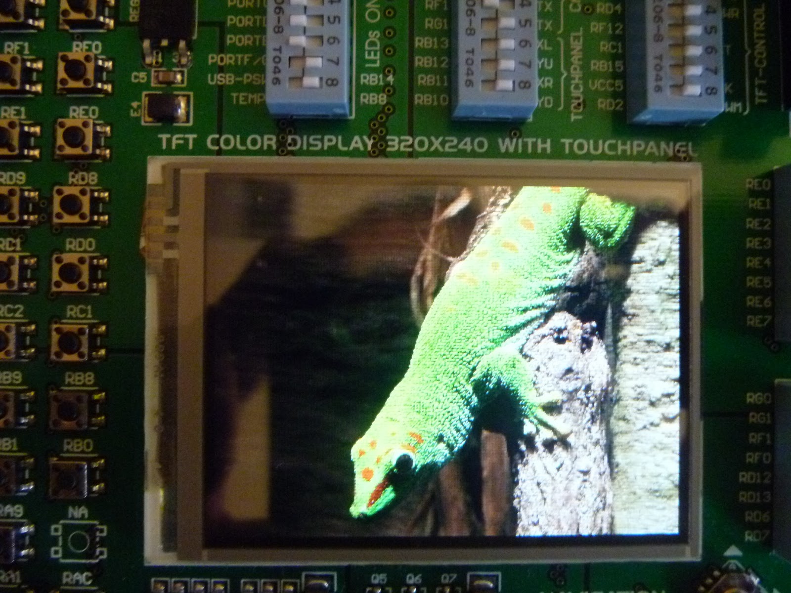
Fired up the development board and it fell into a roundabout of pics.


Not bad for a little 320x240 display.

Thursday, March 10, 2011

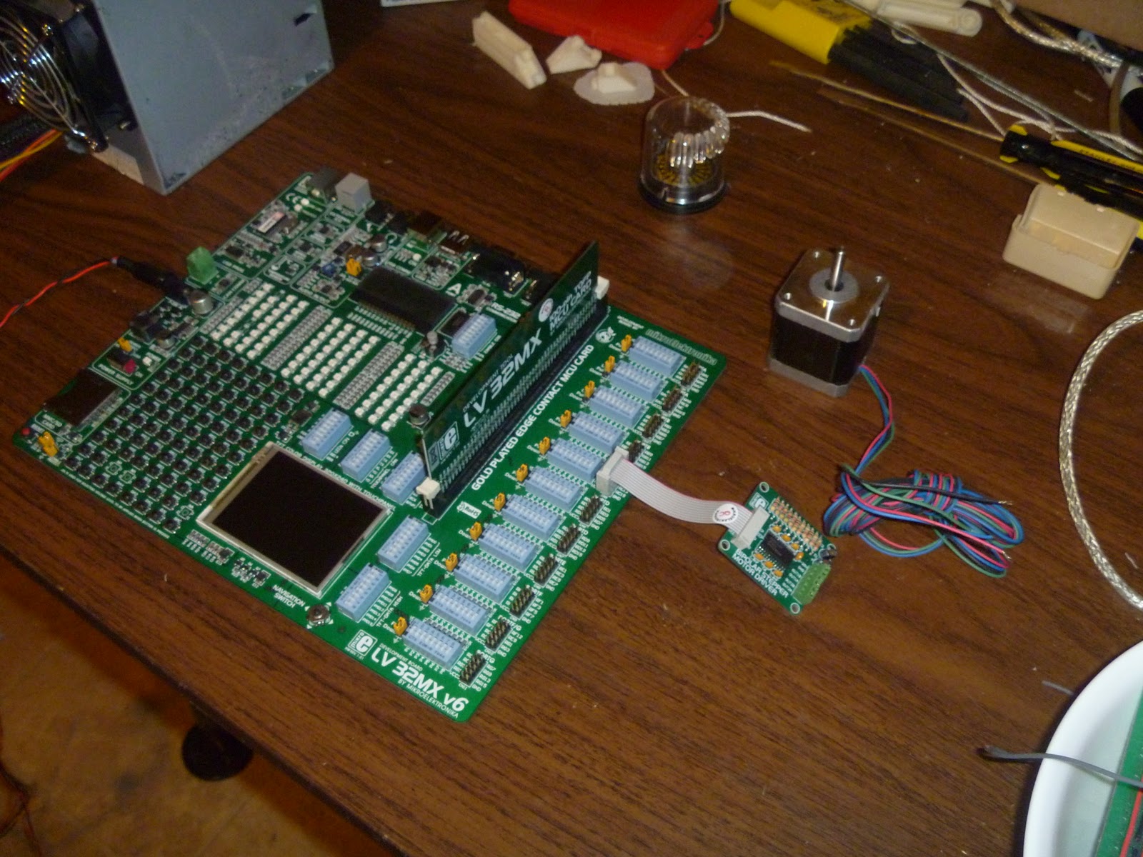
Development board arrived


My PIC32 development board arrived today!


I also got a trial stepper motor controller with it.


The development board looks as good in my hands as it did in the sales literature.

My old PC power supply even had a power connector that fit with the board already installed.  It is a relict of a battery charger for an old Sony digital camera that I finally retired last year.

I am also wanting to adopt Rapman's use of milled linear guides and linear bearings.  If you look hard these are not all that expensive.  For bearings, I found this little unit...


To be well within budget.  Guide shafts are a little pricier.  In the US it appears that 12 mm shafting is the least expensive while still being stiff enough for a printer.  Most pricing seems to be running around $0.50/inch.  That's not cheap, but not impossible.

Being a Scots-Irish tightwad, however, I kept looking for a better deal and ran across this...


...which comes in at a bit under $0.07/inch.   I spoke with the vendor today and they are checking to make sure that it meets CNC requirements for a linear guide.  The general impression was that it did, but I want to be sure.

If that price does follow, it should be possible to replace the effective, but overcomplicated z-axis arrangement of Rapman which derives from the old Darwin design...


...which has 8 mm guide rod and a plastic bushing with a 12 mm guide rod and a proper linear bearing.  That extra rigidity might allow me to control the position of the print table with an single, proper lead screw attached to a cantilever beam which contacts the bottom of the print table in the center instead of three or four lead screws, or cheap studding {threaded rods}, more likely.

Certainly the leveraging the guide rods as vertical structural members should simplify the design a bit.

Tuesday, March 01, 2011

Going for 32 bit embedded processors


In which your narrator begins to cobble a next-generation Reprap controller board together out of much bigger vitamins than has previously been possible.

The controller for the Bits from Bytes Rapman has long been the most sophisticated in the world of Reprap printers. It's use of the PIC32 MCU gives it the power to do things, like support an LCD display, SD cards and 0.1 mm gcode steps without difficulty are very difficult to do with 8 bit MCUs. There are two barriers to it's widespread adoption in Reprap printers, however.

The first is that PIC32s typically come as 100 pin surface mount chips. That means that you have to do some fairly sophisticated PCB design and get the damned chip soldered on properly. That's not impossible, but it's not easy, either.

The big barrier, however, has been the lack of inexpensive compilers for PIC32s. The one from Microchip is very good, but costs over $1K. Recently, that situation has been remedied by a Serbian firm, Mikroelektronika. I had had experience with their PIC 18F compiler and found it both very reliable and possessed of an enormous library of library functions which made it extremely valuable as a development tool.

Thus, when I heard last year that Mikroelektronika had undertaken to create an inexpensive compiler for PIC32 chips I was immediately interested. After a long development and beta cycle they did their formal release this morning.  They offer inexpensive C, Basic and Pascal compilers for the PIC32.

Some time ago, I resolved to build up my next printer rather than buy another BfB product.  The ultra-reliable BfB extruder and controller board were two technologies that I intended to bring across.  I wanted, however, to have two extruders and a somewhat bigger print table to accommodate them better than Rapman allows.

Laszlo created an inexpensive, easier to repair hot end than BfB offers which I also intend to use in the design.


As well, recent purchase of a hobby lathe ...


... will let me experiment with large diameter precision lead screws which can double as structural elements should cut down on the amount of steel in the printer rather dramatically.


The big advantage to the new Mikroelektronika compilers, however, is that they also offer an inexpensive line of prototyping boards.  That will save me the development time of putting together a new board with technology that I am not familiar with.  I ordered their most expensive board {$169}...


which includes everything that I need save stepper drivers.  I also ordered one of their stepper driver boards. to test with it to test my firmware with ...


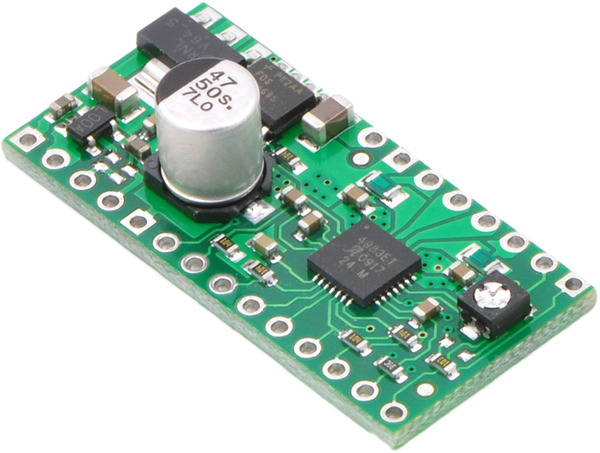
before I integrate the heavier amperage Pololu driver board that has been used in a number of other Reprap controller boards.


The current situation is so much better than we faced when we began the Reprap project in 2005.  Then you were pretty much doomed to building up boards from scratch.  These days you can buy inexpensive boards and add-on miniboards to build up an inexpensive yet very sophisticated Reprap controller board quite easily.

Should my controller design catch on, I suspect that other Reprappers would want to use this much smaller and less expensive graphics board in Mikroelektronika's stable ...


...  which has pretty much everything the larger board does.


Monday, February 14, 2011

Printing small holes in small features


In which your narrator discovers an out-of-the-box method of making small holes for pinned hinges in small features.


Recently, Chris Palmer blogged an exquisite article on the pitfalls of getting the diameters right in holes made in objects. It related very closely to a problem I was having in developing a printed robot hand.


Previously, I'd had no trouble in that the joints between the phalanges of the robotic fingers were very large and printed.


I loved this approach, but sadly had to abandon it simply because the large contact areas between the phalanges created excessive friction and because the number of things that I needed to have happening in a phalang made the large joints unhelpful.  The need for smaller, more compact hinged joints brought to mind the work of Frank Davies with his Sarrus Linkage positioning system.


Frank used pinned hinges to great effect.


As I was designing such pinned hinges into my phalanges, I soon discovered that the substantial pins that Frank was able to use were too large for the delicate phalanges that I was working on.  In fact, I finally settled on using simple paper clips (0.84 mm diameter) for the pins in my work.


In designing the joints, I followed the usual Reprap gambit and simply included the pin holes in the STLs for the parts.


The only problem with this approach was that both the hole and the hinge joint that it was seated in were very small.  The joint had a radius of only 3 mm and the hole 0.42 mm.  


Ordinarily Reprappers use a few print paths around the perimeter and then infill the rest. I design using thin walled parts glued together after printing, an approach that lets me create fine featured parts that are fast to print.  With a feature this small, however, print roads radiating out from the pin hole very quickly clash with print roads radiating in from the joint.


It's bad design practice to let a hot print head hover for extended periods of time over or near a small feature.  You want the head doing the feature then going far away quickly so that the molten plastic thread has a chance to cool a bit before the next layer is applied.  If you don't get this your small feature becomes a featureless blob.


Print road clashing between the pin hole and outer perimeter of the hinge had me fiddling around with print road width for the better part of a week with indifferent results.  Yesterday, however, an out-of-the-box solution to the problem finally hit me.  I'd do better at printing the pin hole if I simply didn't include it in the STL, something like this.


Basically, I just plugged the hole.  What that did is to limit the print road propagation to those radiating inwards from the outside perimeter of the hinge.   Since I don't use infill because of the problems getting the perimeter roads to match with the infill roads, for the first few millimeters of the print had no hole due to the use of perimeter roads to completely fill the layer.


Once I had the roads calculated I pulled up the .PNG images for the completely filled layers.  You can see the bit that will fill the pin hole circled in red.  


It was a simple matter to pull the images into Paint and remove the inconvenient loop from the images and then continue processing the images into Gcode.  


By calculating the width of the print roads appropriately, I was able to get the proper diameter for the pin correct on the first try.


The annoying part of this whole epiphany was that it took me over a week and dozens of trial prints to see the simple way of solving the problem.